Custom Products from Masters Communications

|
Custom Products from Masters Communications |
|
This product was replaced with two new models:
RA DIN-6 Adapter
for the RA Series
DRA DIN-6 Adapter for the DRA Series
Pricing:
Complete Kit - No Longer Available
Assembled and Tested - No Longer Available
US Priority shipping and handling $10.50 in small quantity.
First-Class shipping available to most locations worldwide, calculated at checkout.
PayPal accepted - order below.
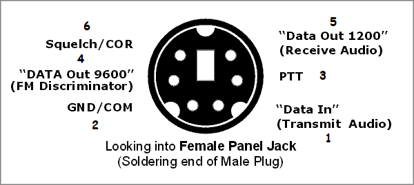
DIN Pinout Illustration:
Click to view larger image.
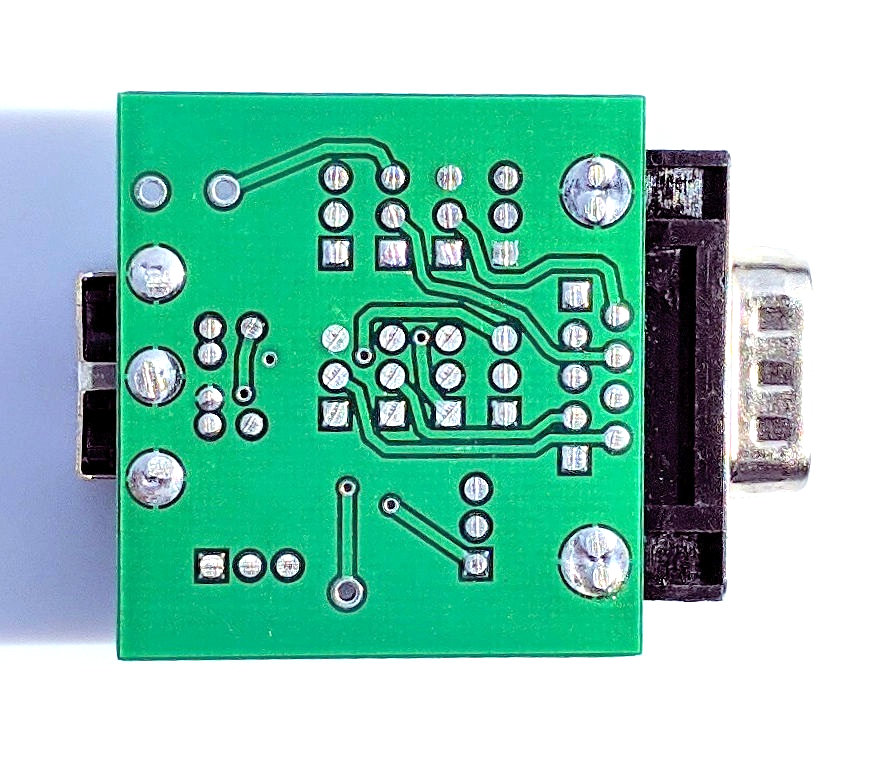
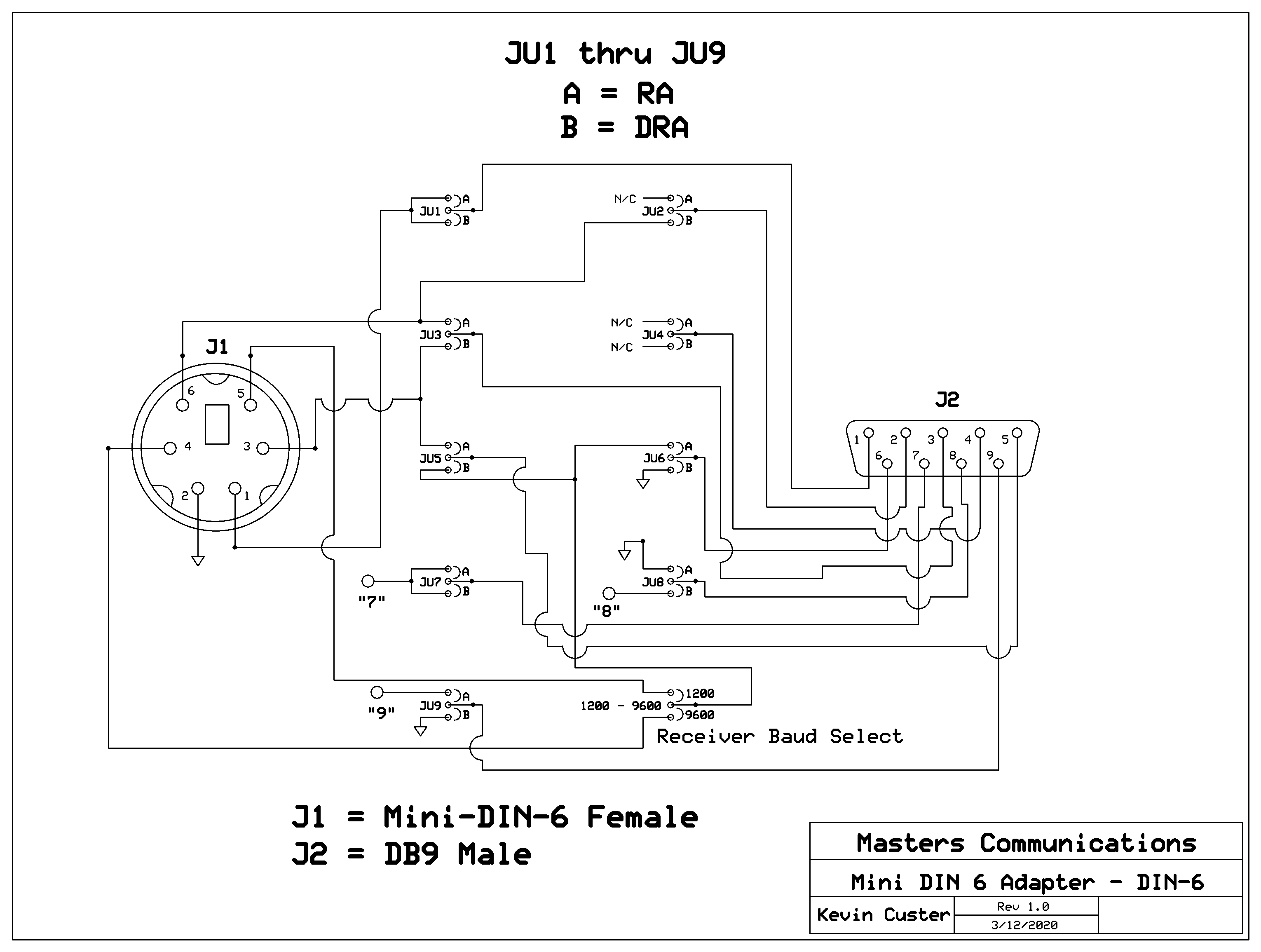
Schematic Image:
For larger view - right click to "View Image" or left click to download a PDF.
This connector adapter attaches to any radio adapter with a DB9 available from Masters Communications. It converts the DRA-30, DRA-45, DRA-65, and all RA-Series radio interfaces to Mini-DIN-6. It allows an inexpensive DRAC-12 cable to be used between the radio adapter and radios with a Mini-DIN-6 accessory (data) connector.
This adapter is not for adapting DB9 connectors on radios.
Easily movable jumper "shorts" allow this product to be used with either the RA or DRA Series radio adapters. Move all 9 "JU" jumpers from one position to the other to complete the configuration. In other words - JU1 through JU9 select between the RA and DRA series. All 9 of these jumpers get moved to either the "A" or "B" position to select between the two series.
There is no "A" or "B" position to the baud jumper. The selection of baud operates independently from those 9 jumpers. This allows selection between the 1200 and 9600 baud receiver audio from the radio - no matter what type of radio adapter (RA or DRA) that you have connected to the adapter board. The reference to A and B doesn't intentionally have anything to do with dual band radios or their "side".
The Male DB9 connector on this board attaches securely to the radio adapters Female DB9 with the provided screws.
Detailed Description:
There are a total of ten 3-pin headers and jumpers (shorts). Selection of RA
or DRA is easily done by moving the 9 "JU" jumper shorts from position "A" to position "B".
These positions are plainly silk screened onto the board. The two positions of
these movable headers/jumpers select between the RA Series and DRA Series. In other words,
they have nothing to do with the way the DIN connector is wired, and everything to do
with the way the DB9 is wired. The DIN wiring configuration stays the same (as shown in
the image below) wired for many radios, like the Yaesu FT8800R. Remember - all 9 of them need to be in either
the A or B position to configure it correctly.
A tenth movable header/jumper selects either 1200 or 9600 baud receiver audio. The selection of baud operates independently from those 9 jumpers. This header doesn't have an A/B silkscreen, it says 1200 - 9600. All it takes to move these jumpers is a pair of needle nose pliers.
Optional Connections:
Three optional connections are available for wiring up optional things, stuff that I
may not have thought of, or, are beyond the original scope of this board.
These connections are "holes" which are labeled "7" "8" and "9". They are available when
the following jumpers positions are set:
Hole 7 = Either position "A" or "B" - COMM OK or Alarm Logic (RA or DRA)
Hole 8 = Position "B" - Left Channel TX Audio (DRA only)
Hole 9 = Position "A" - External power for audio amps and filters (RA or DRA).
Examples and explanations of these optional connections:
An example for Hole 7 is the opportunity to connect to the "COMM OK" health status "Alarm
Logic" on either the RA or DRA. This option is available on all radio adapters except the
RA-25 and DRA-30, and is fully explained on the "Descriptions" pages.
An example for Hole 8 is access to the DRA left channel audio output. It may be necessary in some installations to create the PTT signal from an external VOX circuit. This is currently the case for VARA HF, and some other digital programs where the programmer has not yet implemented the CM119A GPIO3 keying method used in all Masters Communications radio adapters. Access to this audio output is enabled when JU8 is placed in the "B" position, and a DRA Series interface is connected. Many of these programs duplicate the data audio on both channels, and this one can be used independantly to feed the VOX circuit.
An example for Hole 9 is to supply external voltage to the amplifiers or filters on either the RA or DRA on DB9 pin 9. Some installations may require more audio or audio that has been filtered. The normal voltage to the amps and filters is 5 volts as supplied from the USB. When 5 volts isn't enough to run these amps and filters, a connection to an external (12V) power source is needed. This option is fully explained in the "Descriptions" pages and FL-10 filter page.
This product was replaced with two new models:
RA DIN-6 Adapter
for the RA Series
DRA DIN-6 Adapter for the DRA Series
Email Kevin Custer for ordering information, ordering by check, and/or support of this exciting product.
Product of Masters Communications, all rights reserved.
Specifications may change without notice.
Images are property of Kevin Custer - W3KKC
Board layout by Kevin Custer - W3KKC
HTML March 10, 2020, W3KKC All Rights Reserved!