the Masters Communications
FTDI USB to TTL Adapter
By Robert W. Meister WA1MIK

|
Design and Evaluation of the Masters Communications FTDI USB to TTL Adapter By Robert W. Meister WA1MIK |
|
Background:
This project started in April 2020 as an offshoot of needing to program a Motorola PM1200 low-band mobile radio. This particular radio is programmed through its modular microphone jack on the control head. I had a pre-made USB programming cable for that and it worked fine. I also had my RIB and modular radio cable; they worked fine too. The PM1200 radio unfortunately requires a special cable that plugs into the 20-pin Accessory Connector on the back of the radio for use by the alignment software. I was reasonably sure that the pins labeled TXData and RXData needed to be used and I figured that the PTT input was also used to key the radio when adjusting the transmitter power, frequency, and deviation. There is also a Boot Control signal on the Accessory Connector and I had no idea if that needed to be activated as well.
All of the radio signals are TTL, 0-5V. I had an RS-232 to TTL serial programming cable that worked fine with my GE MLS-2 radios and considered making a short adapter cable to connect that to the PM1200 TXData and RXData, but I had no idea how the software caused the transmitter to turn on. Did it use the PTT Input on the Accessory Connector or issue a command to the radio via the serial data lines? I felt I needed a serial port breakout box with LEDs so I could see what signals were being activated. I purchased a small DB-9 serial port monitor for about $10 just for this purpose.
What's Available:
The USB programming cable used to program the PM1200 is based on an FTDI RS-232 chip that WinXP Home edition recognized automatically and assigned a virtual COM port to allow programs to access that device. These virtual COM ports are usually COM4 and higher. Most Windows software will allow you to choose a real serial port or a virtual one. In this case, the PM1200 programming software had no problems using the USB cable and COM5 and this worked perfectly right out of the box.
Based on comments about USB to serial cables, I started looking around for USB to TTL adapters or cables that used the FTDI chip set. I found thousands of them. Most had a 6-pin connector for the TTL side, providing TXData, RXData, Ground, +5V, but only two handshaking signals, even though the USB chip has all of them available. I had no idea which of the six serial port handshaking signals I might need to make a programming cable that would work with the PM1200's alignment software.
I made a suggestion to Kevin on April 21st that this might be a nice mini-project if he had some spare time. We hashed out some details and requirements and a few days later it seemed to have piqued his interest. I wanted LEDs on every TTL signal and I wanted to use a genuine FTDI chip, not an Asian counterfeit, because it seemed to be the one that was most compatible with Windows and serial communications programs, including many radio programming cables. I found one adapter that we used as the basis for our FTDI USB to TTL adapter.
A Mini-Project is Born:
In the beginning of May Kevin presented me with the first of a dozen circuit board layout designs, which we refined over the next four days. He ordered some circuit boards and parts, and built one unit when he received everything. He mailed me that assembled unit as a model plus an un-built kit with the two surface-mount components pre-installed. I created a parts list and schematic diagram. I found a free serial port monitor and terminal program (Termite) that would let me set, clear, or view the six serial port handshaking lines and it seems to work fine with virtual COM ports.
I received one pre-assembled prototype unit on May 20 and plugged it in to my WinXP Professional edition system. The system detected "new hardware" but couldn't find a driver for the FTDI chip, so I went to FTDI's web site and downloaded the last WinXP 32-bit driver package 2.08.24 and let Windows install that when I plugged my USB cable back into the unit. Once completed, I fired up the Termite program and did a brief check of the unit. I could turn the two output handshaking lines on and off, and grounding any of the input lines caused the respective LED on the board and the indicator in Termite to light up. The TXD LED also briefly flashed when I sent out some characters. Further testing will be done with some loop-back clip leads attached.
Kevin sent me a Rev 1 board in July 2020 and I assembled it in August 2020. The only differences from the prototype are that the pin layout for J2 follows the standard DE-9 pin numbering and arrows were added next to the signal names to indicate their direction (in to or out of the board). This unit is now known as the "Ultimate FTDI".
Kit Assembly:
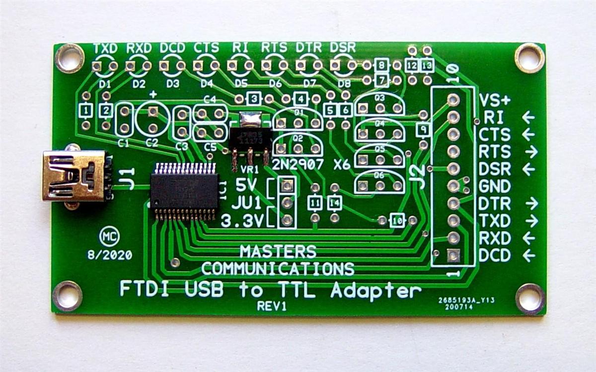
The current Rev 1 board is 2.9 inches wide by 1.6 inches high. It comes with the surface-mount FTDI chip, 3.3V regulator, and mini-USB jack pre-installed. As usual, this is a high-quality circuit board that is easy to work on and repair if necessary. Here's a photo of the unassembled board. Click on any photo below for a larger view.
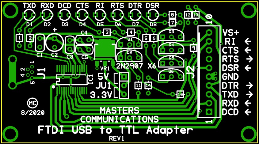
The original artwork showing the component designations, square solder pads, etc, might be easier to view while assembling the kit. It's being provided below with the grateful permission from Kevin W3KKC.
Refer to the parts list here. I always print this and verify
that each part is present before I begin assembly of any kit.
Refer to the schematic diagram here.
As usual, I install the shortest components (closest to the board) first: the resistors. Some of the color bands are hard to discern. For example, the 4.7k resistors have a yellow band at one end that's about the same color as the tan resistor body. Luckily there are only three unique resistor values so you can install them in sequential order: the 330 ohm, and six 2.2k resistors first, leaving only the six remaining 4.7k resistors to place last. I always use my DMM to measure these 1/8w resistors, because I don't trust my eyes to read the colors properly. There are 14 resistors to install; each location has a square box with a one or two digit number in it. Note that only the numerical portion of the part number is on the silkscreen (no letter 'R') for the resistors; all other parts have their full part ID shown. Bend the leads into a "U" shape as close to the resistor body as you can, flat against them if possible, then stuff them into the board, pull the leads all the way through so the resistors are flat against the board, and solder them. I installed them in sequential order in three groups: R2, R3 through R8 (all the same value), and finally R1 and R9 through R14 (all the same value).
The four ceramic capacitors (marked 104) C1, C3, C4, and C5, get installed in their locations. Polarity is unimportant.
The various LEDs, D1 through D8, are next. The TXD LED D1 is red, the RXD LED D2 is green, and the remaining (handshake line) LEDs are yellow. One of the LED's leads is longer than the other; this longer lead goes into the hole with the round solder pad; the shorter lead goes into the hole with the square solder pad. The long lead of LEDs always goes in the round hole. This is an industry standard. So when you're assembling the kit, the long lead has to be inserted first, and placing it into the round hole makes sure the polarity is correct. There's also a barely detectable flat edge along the base of the LED on the same side as the shorter lead; disregard the flat; go by the lead length. Install the LEDs flush to the circuit board for stability. I installed them in two groups, which gave me space to solder them: D1 (red), D3, D5, D7 (all yellow), then D2 (green), D4, D6, and D8 (all yellow). I soldered one lead of each LED (the one in the round pad), then reheated it and pushed the LED all the way down onto the board and made sure it was straight, then soldered the other lead (the one in the square pad).
The single electrolytic capacitor C2 gets installed in its round hole. The negative lead of the capacitor is marked with a white stripe on the capacitor body. The positive or opposite lead goes into the square solder pad hole next to the "+" mark indicating polarity. Install this capacitor flush to the circuit board.
The six PNP transistors are next. Spread the leads slightly and align the flat with the outline on the board. Let them stick up off the board about 1/8 of an inch, or twice as high as the resistors. I installed them in two groups: Q1, Q3, Q5, then Q2, Q4, and Q6, to allow for space to get the soldering iron to the leads. After I installed the first group and made sure they were straight and at the same height, I used those as a gauge to set the height of the remaining group.
The three-pin header JU1 is next on the list. Install it flush to the circuit board. Solder one pin first, then reheat it and straighten out the header and push it down to the board, then solder the remaining pins.
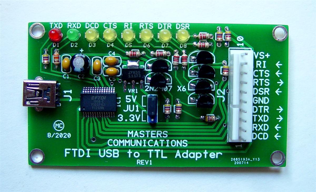
The last piece is the 10-pin male connector J2. Install this with the locking clamp towards the inside of the board, over the thicker area of the component outline. As with most of the other components, install this flush to the circuit board. Solder one pin first, then reheat it and straighten out the connector and push it down to the board, then solder the remaining pins. Here's a photo of the assembled board I built.
I cleaned the solder side of the board with 91% isopropyl alcohol and a toothbrush. Check for solder bridges, especially around the mini-USB jack J1. All the other solder pads are spaced far enough apart that a solder bridge is virtually impossible. My kit took just over an hour to assemble as I was being overly cautious and taking notes for this article as I went.
Basic DC Tests:
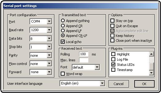
I set JU1 to the 5V position. I plugged my mini-USB cable into the unit and let the software wizard do its thing to install the driver that I had previously downloaded. I had previously installed Termite with all its plug-ins but only activated the one that displays the Status LEDs. Note that the only plug-in that's enabled is Status LEDs; none of the others are checked off. The program's settings are visible in the screen shot below.
I connected a clip lead between ground (pin 5) and each of the other input lines and observed the associated LED on the board and the indicator in Termite light up.
I connected five clip-lead jumpers to the pins on J2, to loop back the various signals, as described in the table below. The pin numbers are also listed in parentheses.
| Source or Output | Destination or Input |
|---|---|
| TXD (3) | RXD (2) |
| RTS (7) | CTS (8) |
| RTS (7) | DSR (6) |
| DTR (4) | RI (9) |
| DTR (4) | DCD (1) |
By clicking the RTS icon in Termite, the CTS and DSR icons should light up and their three yellow LEDs on the board should light up. Similarly, by clicking the DTR icon in Termite, the RI and DCD icons should light up and their three yellow LEDs on the board should also light up. Clicking the icons again will turn off the indicators and LEDs.
You can also type data into the one-line window at the bottom of Termite's screen and it will be displayed in the window at the top. Both the red TXD and green RXD LEDs should light up depending on how much data you type. You can also ground just the RXD data line and the RXD LED and icon should flicker briefly.
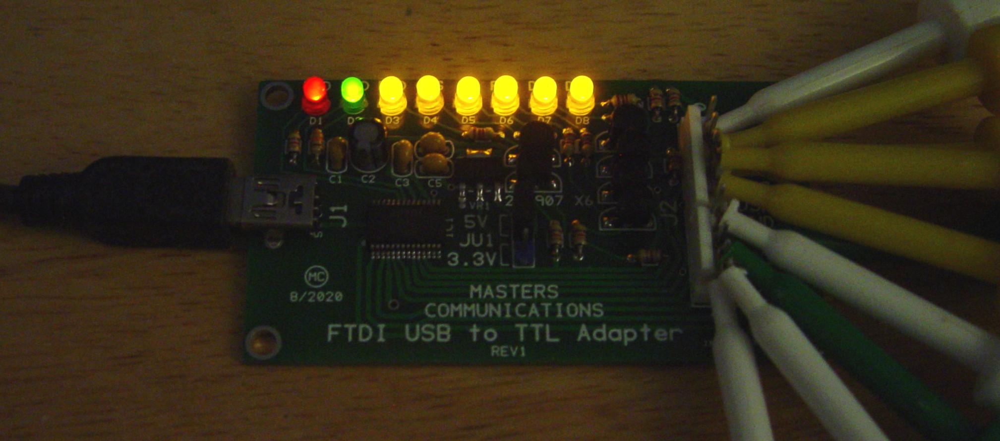
I turned on the two output lines in Termite; that caused all the handshake lines to become active and their respective LEDs lit up. I also typed several hundred characters into Termite and when I pressed ENTER that data got sent out, which lit the red and green LEDs. Here's a photo taken with ambient light to show all of the LEDs lit up.
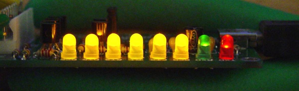
And here's a side view of the lit LEDs.
You can change JU1 to the 3.3V position and repeat the above tests and everything should look basically the same except the LEDs might be slightly dimmer.
All of the signals on J2 are active-low and are pulled to ground by the FTDI chip or the external signal. Turning on a signal via the USB port will cause its corresponding pin on J2 to go low and its LED to light up. An RS-232 marking level (a negative voltage) corresponds to a high level on J2, while an RS-232 spacing level (a positive voltage) causes the pin on J2 to go to ground and its LED to light up.
I even removed JU1 entirely and plugged the unit in. As expected, none of the board's LEDs lit up, and all the handshaking input signals appeared to be active/on as they were pulled down low enough. I was unable to turn on any of the LEDs through Termite. After reinstalling JU1, the unit operated as it had previously with no signs of damage.
What Remains to be Done:
I now have to wire up a PM1200 20-pin Accessory Connector, plug it in, and run the alignment software to see if I can at least read the radio's alignment data and also determine which handshaking line is used for PTT. That's really all I came here to do.
Credits and Acknowledgements:
Product information for the Masters Communications Ultimate FTDI USB to TTL adapter board can be found here.
The FTDI FT232R USB chip datasheet and drivers can be found here.
Termite Version 3.4, a simple RS-232 Windows terminal program, was obtained here.
Contact Information:
The author passed away in June 2021. He is greatly missed - W3KKC
This page originally posted on Friday 22-May-2020
Article text, artistic layout, all photographs, and hand-coded HTML © Copyright 2020 by Robert W. Meister WA1MIK.
This web page, this web site, the information presented in and on its pages and in these modifications and conversions is © Copyrighted 1995 and (date of last update) by Kevin Custer W3KKC and multiple originating authors. All Rights Reserved, including that of paper and web publication elsewhere.