Masters Communications
SC-75 Noise Squelch
and CTCSS Decoder
By Robert W. Meister WA1MIK SK

|
Evaluation of the Masters Communications SC-75 Noise Squelch and CTCSS Decoder By Robert W. Meister WA1MIK SK |
|
Noise Squelch Product Family:
The MS-25 is an analog noise squelch detector that uses a Motorola MICOR squelch chip for its squelch processing. It's an SC-50 without the CTCSS chip.
The MS-50 is an analog noise squelch detector that uses a functionally equivalent circuit to replace the Motorola MICOR squelch chip. It's an SC-75 without the CTCSS chip.
The SC-50 is an analog noise squelch and CTCSS decoder that uses a Motorola MICOR squelch chip for its squelch processing. It's an MS-25 with the CTCSS chip.
The SC-75 is an analog noise squelch and CTCSS decoder that uses a functionally equivalent circuit to replace the Motorola MICOR squelch chip. It's an MS-50 with the CTCSS chip.
Here's a graphical representation for those of you who don't like to read.
| Feature | MS-25 | MS-50 | SC-50 | SC-75 |
|---|---|---|---|---|
| Squelch Type | MICOR IC | Equiv. Ckt. | MICOR IC | Equiv. Ckt. |
| CTCSS Decode | No | No | Yes | Yes |
This article specifically covers the SC-75. The other products in this family are extremely similar and the noise squelch operates exactly the same way.
Familiarization:
I thoroughly read the available web pages for this product several times before assembly. I
also created a parts list sorted by component value, so I could reach into the pile of parts,
grab one, determine its value then see where to insert it. Since there are well over 100 parts,
this seemed to be a better way to build the kit rather than to sort the parts then go looking
for a specific one based on where it might go.
This sorted
SC-75 parts or this this sorted SC75DW
parts list as a short PDF file. You should print this file to assist you
when building the kit. Kevin and I agree that the parts should be inserted with the shortest
ones first (resistors, diodes, capacitors, transistors) and ending with the tallest/biggest
ones (electrolytic capacitors, DIP switch, and the DB25 connector). The resistor leads should
be bent as close as possible to the resistor bodies before inserting them, so they fit flush
to the circuit board. I installed the parts in the group order in the above sorted parts list.
Here's a photo of the bare circuit board; click on it for a larger view.

The circuit board is the typical high quality that is standard with all Masters Communications products. The parts are very densely packed on this product. Resistors numbered R10 and higher are indicated just by their two-digit identifying number on the silk-screened circuit board, inside the component's location outline. Other parts have the full component designation. Here is the silk-screened parts location diagram as a short PDF file, which might be easier to use to find where some parts go, rather than staring at the circuit board. If you have a color printer, print this file as well to assist you when building the kit.
Assembly:
I started with the resistors. I found it much easier to measure each resistor with my AC-powered digital multi-meter than to attempt to ascertain the value by reading the color code. 1/8-watt resistors are SMALL and without a magnifying glass or close-up reading glasses, some of the colors are hard to discern. Luckily the values of the other parts were easier to determine although I did hold some under a magnifying glass to discern the writing.
I had dumped the entire bag of parts into a 6-inch paper bowl. My assembly procedure began as follows:
All of the resistors are installed flat to the board. The leads must be bent very close to the resistor body to make them fit down properly.
What takes the most time is locating where to insert each part. The component designations on the board are VERY small. I installed 6-8 resistors at a time, soldered them, and cut their leads off. My soldering iron was set to 650F. I used Kester "44" rosin-core solder 0.039 inches in diameter, 60% tin, 40% lead.
Even though I measured EVERY resistor, I still made a mistake and ended up with an unused 1k resistor and a missing 10k resistor. Turns out I had measured a 10k but missed the decimal point and read it as 1k, and I installed it where a 1k should have gone. It took a few minutes to verify all the 1k resistors and find the one that wasn't 1k; I re-measured it and it read 10k, so I took it out, installed it where it belonged, and put the leftover 1k resistor in its place. Problem solved. It was quite easy to fix it at this point, when I had installed only the resistors.
When you install a resistor, that hides its component designation and that makes locating one later much more difficult. There might be a better way to install them, such as finding all the 1k resistors, installing them, finding all the 10k resistors, installing them, etc, just because there are so many of those and the colors are so close.
I found the violet bands looked black, the yellow bands were almost tan, and the gray bands were almost white. Don't go by the color code; measure every one. None were exact; the tolerance is at least 5% and closer to 10% for some values.
More Assembly:
I removed some of the larger components from my parts bowl: the DB25F, the DIP switch, the crystal, the headers, the pot, and the electrolytic caps. I then installed the diodes, the LEDs (the short leads go into the holes with the square pads), the transistors (marked "N" for NPN 2N2222 or "P" for PNP 2N2907) and voltage regulators (flat to flat on the silk-screen), and the silver mica and tantalum capacitors, observing polarity on all diodes and polarized capacitors. I did these caps first because it was easy to read their values. The banded ends of the diodes, and the positive end of the tantalum capacitors, go into the holes with the square pads. The silk-screen also has bands for the diodes and plus signs for the tantalums.
I installed all the small capacitors next. There are several values that go into multiple locations; I did those first, followed by whatever was left in my bowl of parts. These are identified as follows: "102" = 1000pF or 0.001uF, "103" = 0.01uF, "104" = 0.1uF; in other words, the first two digits are the value and the third digit is the number of zeroes you add to that to get the final value in pF. There are some small dots or lines next to one of the solder pads for some capacitors; ignore these when building this kit.
Next, I installed the aluminum electrolytic capacitors (the positive ends go into the holes with the square pads), the headers, the potentiometer, the 6-position DIP switch (the word "ON" is silk-screened and goes towards the DB25F connector), the crystal, and lastly the DB25F connector with some of its optional hardware. I installed jumpers on SJ1, SJ3, SJ5, and SJ6. I basically followed the sorted parts list group order.
After each major component group was installed, I cleaned the back of the board with 91% isopropyl alcohol and a toothbrush. At the end I used a quick spray of commercial flux remover to thoroughly rinse off all residue.
I took my time and triple-checked all parts values and placement. It took me 3-3/4 hours to assemble this kit in four 1-hour sessions over three 90 degree days. I wrote this article and refined the sorted parts list as I progressed. Kevin told me it takes him 1-1/2 hours to build one, but I'm betting he has all the parts already sorted in bags or drawers and he doesn't have to thoroughly measure or closely look at each part as he goes. Here's a photo of my completed unit; click on it for a larger view.

Preliminary Board Tests:
Besides a quick visual examination, I made some quick ohm-meter tests on the power input line, then applied 14VDC input power, noted the quiescent current, and measured the 5V regulator output, the 9.6V regulator output, and the 4.8V bias supply. All were well within design and component tolerances at 5.02V, 9.64V, and 4.76V. The 9.6V supply ran out of regulation with 11.5V input power. Current draw with 14V input power is shown in the table below. I used a 10 kHz audio tone to simulate the noise and thereby close the squelch. The DIP switches were set for a 100.0 Hz CTCSS tone.
| Illuminated LEDs And Condition That Caused It | mA |
|---|---|
| No LED (noise signal input, squelch closed, SJ6 removed) | 40 |
| Yellow LED (noise signal input, squelch closed) | 45 |
| Blue + Green LEDs (no noise signal input, squelch opened) | 65 |
| Blue + Green + Red LEDs (squelch opened, decoding CTCSS) | 80 |
Live Testing with a Receiver:
I was mainly concerned with the noise squelch portion of the board, since I had previously performed tests on an SC-50, which I still had. This allowed me to connect both an SC-50 (which uses a MICOR squelch IC) and the SC-75 (which uses a functionally equivalent circuit) to the same receiver to test and compare both boards under the same conditions. The jumper functions and input and output signals are identical between the SC-50 and SC-75 products. The SC-50 loads its discriminator input with a 10k resistor (squelch pot) while the SC-75 has a higher input impedance input amplifier.
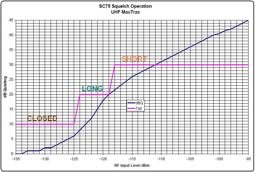
Tests included measuring the squelch opening sensitivity as well as the long-to-short squelch tail threshold, which is typically 20dB Quieting with the MICOR squelch IC.
I used a UHF MaxTrac mobile radio, since I had several lying around. A coaxial relay between the signal generator and receiver's antenna jack was used to turn the RF signal on and off and to trigger the scope. An AC voltmeter was connected to the front panel MIC jack pin 8 (Headset Audio) as this is de-emphasized and at a fixed level; this was only used to measure the dB Quieting level. The radio's squelch was fully opened. The test setup is detailed in the diagram below.
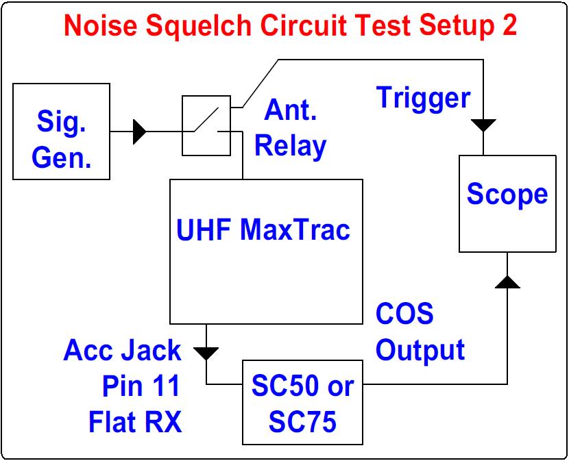
JU551 inside the radio was set to the "A" position for flat/unmuted audio. The audio level coming out of the RX Audio pin (11) of the Accessory Jack was 800mVAC, which is higher than the recommended 1Vp-p (350mVAC) input signal, but it didn't seem to affect either the SC-50 or the SC-75. Both operated flawlessly, including decoding a CTCSS (PL) tone. The squelch opened at a level of -125dBm and had a long squelch tail. 20dB Quieting occurred at -118dBm, at which point the squelch tail changed to a short duration.
I brought the COS Output (DB25 pin 17) out to a wire to provide a convenient spot to measure the timing with an oscilloscope. I set the squelch pot (with no RF input signal feeding the receiver) so the yellow CAL LED was always on and the blue and green LEDs were always off. As I increased the RF input signal level, the LEDs started flickering, then the yellow LED stayed off and the blue and green LEDs stayed on. This happened at a relatively weak signal level that produced about 4dB of noise quieting, at -125dBm. I turned the RF signal on and off and observed the transition time of the blue and green LEDs to see when they changed from staying on briefly (long squelch tail) to immediately going off (short squelch tail) as I increased the signal level. This transition was slightly dependent on how tight I set the squelch, but it happened around -118dBm, which was around 20dB Quieting. I substituted an SC-50 for the SC-75 and it opened and closed and transitioned from long to short at the same points. The table below summarizes the opening and closing times in milliseconds for strong (-100dBm) and weak (-120dBm) input signals, which produced short and long squelch tails respectively. These times are the average of 5 tests. The signal level I used produced a nice long squelch tail.
| Condition | SC-75 | SC-50 |
|---|---|---|
| Strong Open | 26 | 42 |
| Weak Open | 27 | 45 |
| Strong Close | 12 | 10 |
| Weak Close | 190 | 180 |
Test Equipment:
Agilent E4430B RF Signal Generator
Fluke 189 Digital Multi-Meter
Fluke 199C Digital Oscilloscope
Contact Information:
The author died unexpectedly in June 2021. He is sadly missed.
This page originally posted on Saturday 06-Jul-2019
Article text, artistic layout, all photographs, and hand-coded HTML © Copyright 2019 by Robert W. Meister WA1MIK.
This web page, this web site, the information presented in and on its pages and in these modifications and conversions is © Copyrighted 1995 and (date of last update) by Kevin Custer W3KKC and multiple originating authors. All Rights Reserved, including that of paper and web publication elsewhere.