Custom Products from Masters Communications

|
Custom Products from Masters Communications |
|
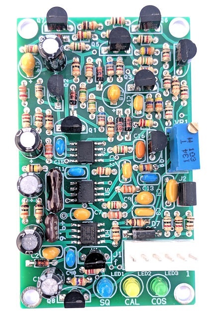
Model MS-50
Actual Size MS-50 PC board.
(Click image to enlarge)
Schematic Image.
(Click image to download a PDF copy)

Overview:
This board will provide quality logic signals for driving a repeater controller or other radio
interface device like URI, RIM, or FOB. It requires discriminator audio and a source of DC
power. It doesn't mute or control the audio path in any way. It uses circuitry to provide
operation similar to the famous Motorola MICOR SC6709 squelch IC.
Assembly:
If you purchased our kit, refer to the parts list and make sure you have all of the components
you need to build it.
Click here
for Parts List.
Assembly can be done by personal choice, but you may find it easier to install the resistors
first, followed by the diodes, capacitors (observing polarity on diodes and electrolytics!),
then transistors (flat to flat on silkscreen). Install the voltage regulator IC and squelch
control. Install the LEDs and six pin header.
Installation:
This device is intended to be installed inside a radio or project box for protection. Refer
to the schematic for the pinout of the 6 pin Molex connector where all of the logic signals,
power connections, and discriminator audio input is listed. The board requires 12 VDC nominally,
and will accept 11 to 16VDC, while surviving 24VDC. A regulated voltage source is not required, but
the source must be clean. Current draw is less than 100mA under all conditions, and is typically
under 50mA squelched, and under 75mA unsquelched. Current draw in the squelched (stand-by) state
can be reduced a little by removing the jumper short from the RED J2 header.
Discriminator Input Level.
The board is designed for 1.5V P-P of discriminator audio from your receiver. If your audio
is too hot, a simple voltage divider comprised to a pair of appropriately sized resistors can
be used to cut the discriminator audio down feeding the MS-50. If the audio from your receiver
is really low, you can optionally use a 100k resistor in location R4 to increase the gain of
the buffer stage. Depending on your repeater / radio, you may need to do one of these things
to get the right amount of audio into the MS-50 for optimum performance.
Setting the squelch.
Once built, installed, and operating properly, the squelch can be set by turning the control
counter-clockwise until the "SQ and COS" LEDs illuminate. Then turn the control in a clockwise direction
to close the squelch. The MS-50 has an additional LED (Yellow) for a visual aide in setting the
squelch control. When setting the squelch control on the MS-50, it's okay (actually desirable)
if the CAL LED flashes. I know it seems that you're setting it on the hairy edge, but just as
long as the "SQ" and "COS" LEDs aren't flashing too, you should be good to go. Of course, if
you like a little tighter squelch, just set it so the CAL LED is on solid. If after setting the
squelch, the CAL LED's flicker bothers you, you can remove jumper J2 to disable this LED. The
squelch pot is a multi-turn type. I have found the board works best with about 1.5V P-P of
discriminator noise (no signal). Too much discriminator audio level makes setting the squelch
difficult - even with a 25 turn pot. The board works fine with audio levels between 0.5V and
5.0V P-P, again 1.5V P-P is best.
Explanation of the logic signals and timing:
Active high and active low outputs for COS logic are available. The outputs are available on
the Molex connector J1. Active high is available on pin 6, and active low on pin 4. Additionally,
a fast-response active low logic signal is available on pin 3. This output isn't normally used,
as it doesn't have the filtering of the latter stages of the logic circuitry. It's intended for
people that want the fastest squelch closing time possible (about 1mS, compared to about 8mS on
pins 4 and 6, with quieter signals. A closing time of about 150mS is expected with signal levels
that are below 20dB of quieting (or so).
A pull-down resistor is included on the active high output. Obviously if you are using this board and need an active low output, you should be using the output at pin 4, but, the on-board pull-down resistor can make circuitry respond correctly when using the active high outputs.
All logic is sourced from +9.6V and ground. +8.7 volts is the maximum voltage expected at pin 6 because of the current limiting resistor R46. A ground is expected at pins 3 & 4. Caution should be given to the use of the two active low outputs, as they are unprotected against over-current (true open-collector), and misuse will cause switching transistor failure. While the active high output has the over-current protection of the 9.6 volt regulator, there is no protection for the active low outputs to ground. Be certain that your connection to these outputs don't exceed the capabilities of the circuit board or NPN switching transistors.
Secure PayPal Ordering - Use down arrows to make your selections.
Quantity can be changed at PayPal after pressing the "Add to Cart" button.
Shipping amount is calculated at checkout for shipping to most locations Worldwide.
Shipping amount is calculated at checkout for shipping to most locations Worldwide.
Email Kevin Custer for ordering information, order by check, and/or quantity pricing of this exciting product.
Product of Masters Communications, all rights reserved.
Inspired by Motorola - (Roy H.
Espe) February 24, 1970
Specifications may change without notice.
Images property of Kevin Custer - W3KKC
HTML June 6, 2019, Kevin Custer - All Rights Reserved!