Custom Products for the Digital Radio Amateur Enthusiast

|
Custom Products for the Digital Radio Amateur Enthusiast |
|
Product Support Documentation
Model DRA-50
A Radio Interface for Digital Two-Way Radio Applications
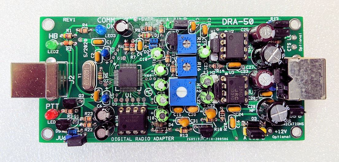
Top side of DRA-50 board - shown slightly enlarged.
(Click photo to show a larger image)
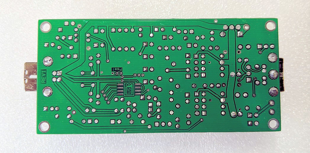
Bottom side of DRA-50 board - shown slightly enlarged.
(Click photo to show a larger image)
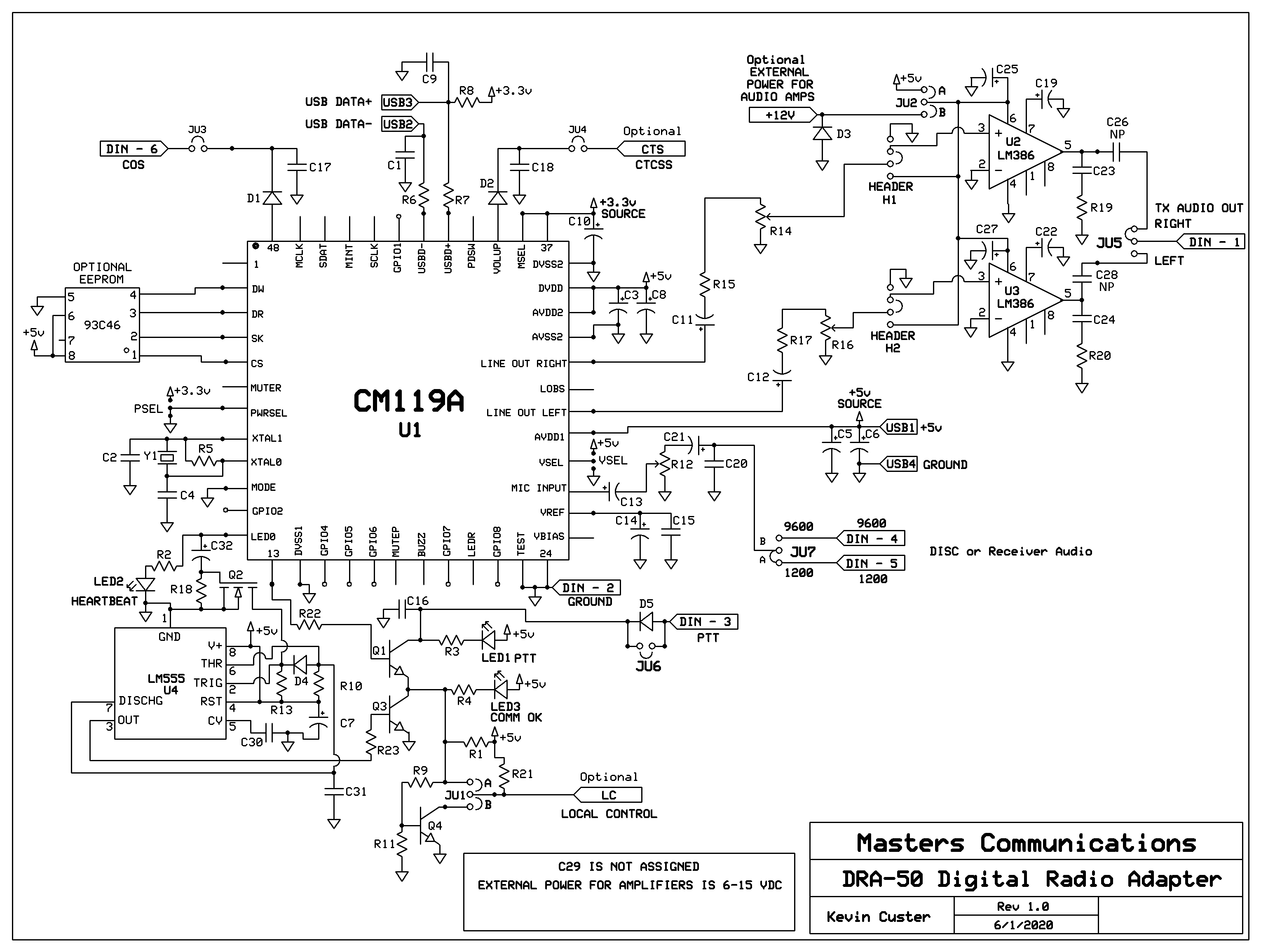
Schematic Image - Click to download a high quality PDF.
Differences between the DRA-36
and DRA-50:
The DRA-50 is similar to the DRA-36, but has these additional features:
1 - High audio output capability, for interfacing those hard to drive
radios.
2 - FL-10 filter capability for when you need to drive the FM modulator
directly.
Parts List:
If you purchased our kit, refer to the parts list and make sure you have all of the components
you need to build it.
Click here
for Parts List.
Construction/Assembly:
Click here for assembly instructions and construction notes - with large photos.
Jumper Settings:
Click here
for Jumper Settings and other board connection assignments.
Mini-DIN-6 Pinout:
Click here
for Mini-DIN-6 Pinout.
Installation:
This device is intended to be installed inside a radio, computer, or project box for protection.
Refer to the schematic for the pinout of the Mini-DIN-6 where all of the logic signals, power
connections, and audio signals are listed.
H1 and H2 header pin assignments:
Click here for a detailed header pin explanation. The
primary purpose of the headers H1 and H2 are for installation of
optional FL-10 audio filters. The FL-10 is designed to be installed onto the header pins
directly or remotely by extending the four pins with wires. Jumpers are needed over the center
two pins if the optional filters are not installed.
Recommended powering requirements:
The board is supplied with 5 VDC from the USB connection. The audio amplifiers and optional
filters can run from this, or from an external power source of 6 to 15 VDC. Jumper JU2 controls
where the voltage is sourced from.
Recommended receive audio input level:
The DRA-50 accepts the widest range of audio compared to any other similar radio adapter. The
input signal is attenuated by a potentiometer, giving the broadest range of acceptable levels.
As little as 20 mV P-P, and as much as 20 volts P-P. If your receive audio level is adjustable
or programmable we recommend around 2.0 volts P-P. This allows very good signal-to-noise
ratio and low cabling cross talk. This level results in a 50% rotational setting of the potentiometer.
Optional Plastic Case:
A Plastic Case is available optionally
for the DRA-50. Available in several colors!
All DRA-50's are supplied with a Genuine C-Media CM119A, but the DRA-50 board was designed to be versatile. It will accept a CM119 (without the A) and even the CM108. There are slight differences between these components, and the board can be 'programmed' to accept any of the three.
Information on the CM119A.
Click here
to download a manual for the C-Media CM119A.
Secure PayPal ordering is available from the DRA-50 main page.
DRAC-12 - 6-foot Mini-DIN-6 Radio Cable can be added optionally to connect several data capble radios to the DRA-50.
Email Kevin
Custer for support, ordering information, order by check, and/or quantity pricing of this
exciting product.
Product of Masters Communications, all rights reserved.
Specifications may change without notice.
Images property of Kevin Custer - W3KKC
Board layout by Kevin Custer - W3KKC.
HTML March 10, 2020, W3KKC All Rights Reserved!