Custom Products from Masters Communications

|
Custom Products from Masters Communications |
|
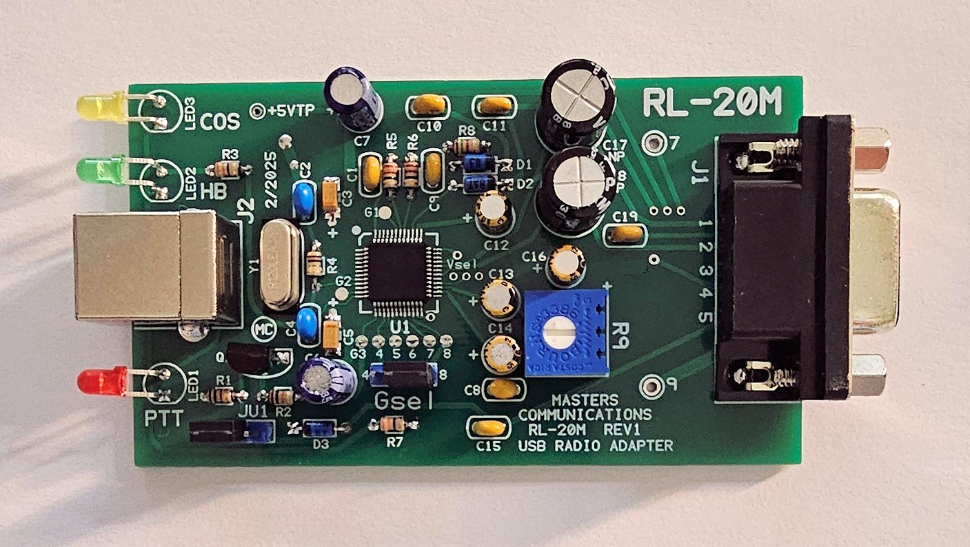
Top photo of the RL-20M PC board.
Click to enlarge.
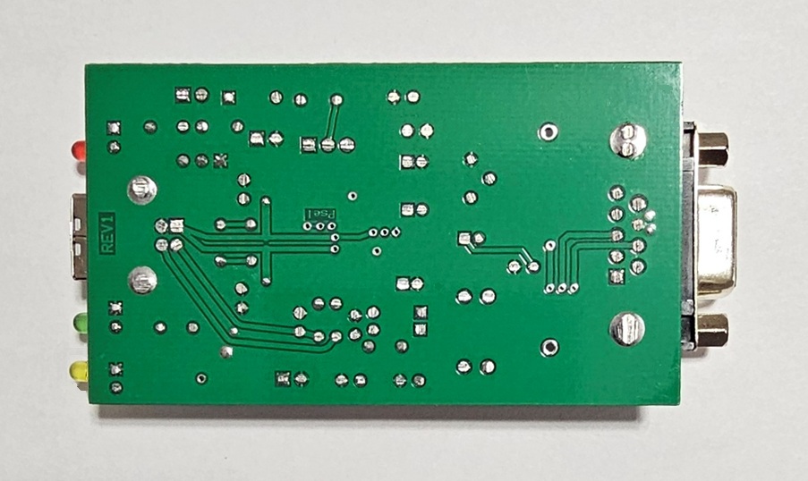
Bottom photo of the RL-20M PC board.
Click to enlarge.
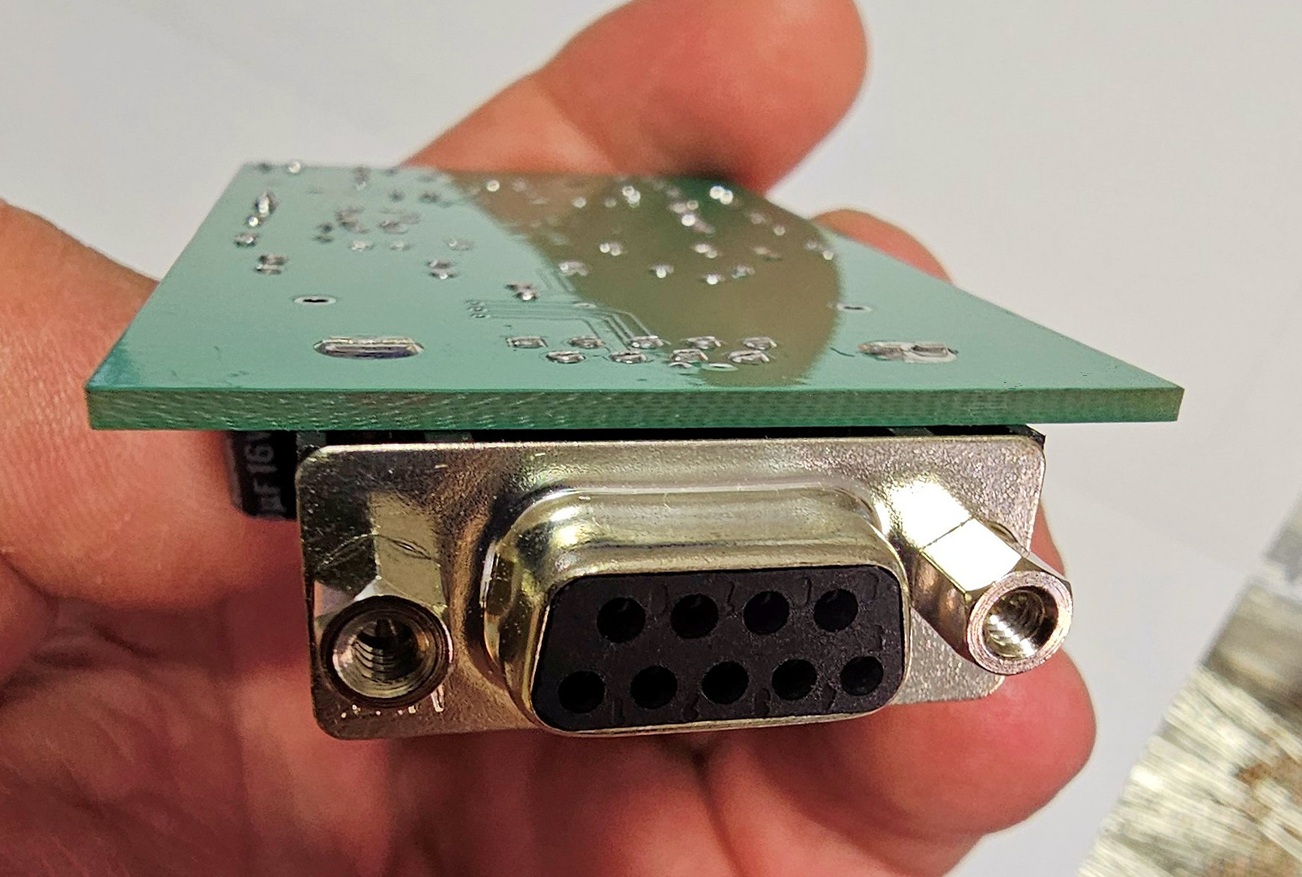
Bottom Edge photo of the RL-20M PC board.
Click to enlarge.
Assembly:
If you purchased our kit, refer to the parts list and make sure you have all of the components
you need to build the kit. All of the components are supplied with the kit, and while we make every effort
to be sure we didn't omit any components, it can happen. If you are missing anything, or ruin
something, just contact us.
Click here for Parts List.
Assembly can be done by personal choice, but you may find it easier to install the shortest components first, building toward the tallest, and finish with the connectors on the ends.
IMPORTANT: When soldering - make sure all of the parts are inserted fully and are tight against the board. This is especially true of the connectors and larger / taller capacitors.
Install all resistors. Some resistors color bands may be hard to make out. If in doubt, use an ohm meter to verify the value before soldering it in place.
Install the diodes and shortest capacitors, observing polarity on all diodes and the polarized capacitors! The square pads are the banded end of the diodes and the + of the electrolytic capacitors. Small capacitors are identified as follows: "47" or "470" = 47pF, "104" = 0.1uF, in other words the first two digits are the value and the third digit (if present) is the number of zeros you add to determine the value.
Install the crystal - with plastic spacer.
Install the potentiometer.
Next, install the transistor (flat to flat on silkscreen).
Now, install the JU1 and Gsel headers.
Next, install the larger capacitors, making sure you keep them flat against the board.
Then, install the DB9F and USB "B" socket connector. Solder the support tabs fully.
Finish by installing the 3 LEDs (short lead to the square hole). Use the front panel as an alignment guide.
IMPORTANT: In order for the board to be installed into the case, all leads and connector
support tabs will need to be trimmed as short as possible with sharp flush cutting pliers.
I use flush cutters from Harbor Freight, but any good sharp
flush cutters should work. Trim the leads and connector support tabs as close to the board's surface
as possible on the solder side. Be careful not to cut traces! Refer to the photos above for reference.
Now - Test your board to make sure it works properly before installing the vinyl sticker and sliding the board into its metal case.
When you're sure it works properly, install the vinyl protective sticker on the bottom (solder) side of the circuit board using careful alignment. While the inner surface of the box is annodized, and therefore electrically insulated, it's best to install the sticker to insure the solder joints don't contact the case.
Information on the CM119A.
Click here
to download a manual for the C-Media CM119A.
Email
Kevin Custer for support.
Custom cables available from URI Cables. They will build a custom cable for the RL-20M for many radios.
Product of Masters Communications, all rights reserved.
Specifications may change without notice.
Images property of Kevin Custer - Masters Communications.
Board layout by Kevin Custer - W3KKC
HTML March 6 2025, W3KKC All Rights Reserved!