Custom Products from Masters Communications

|
Custom Products from Masters Communications |
|
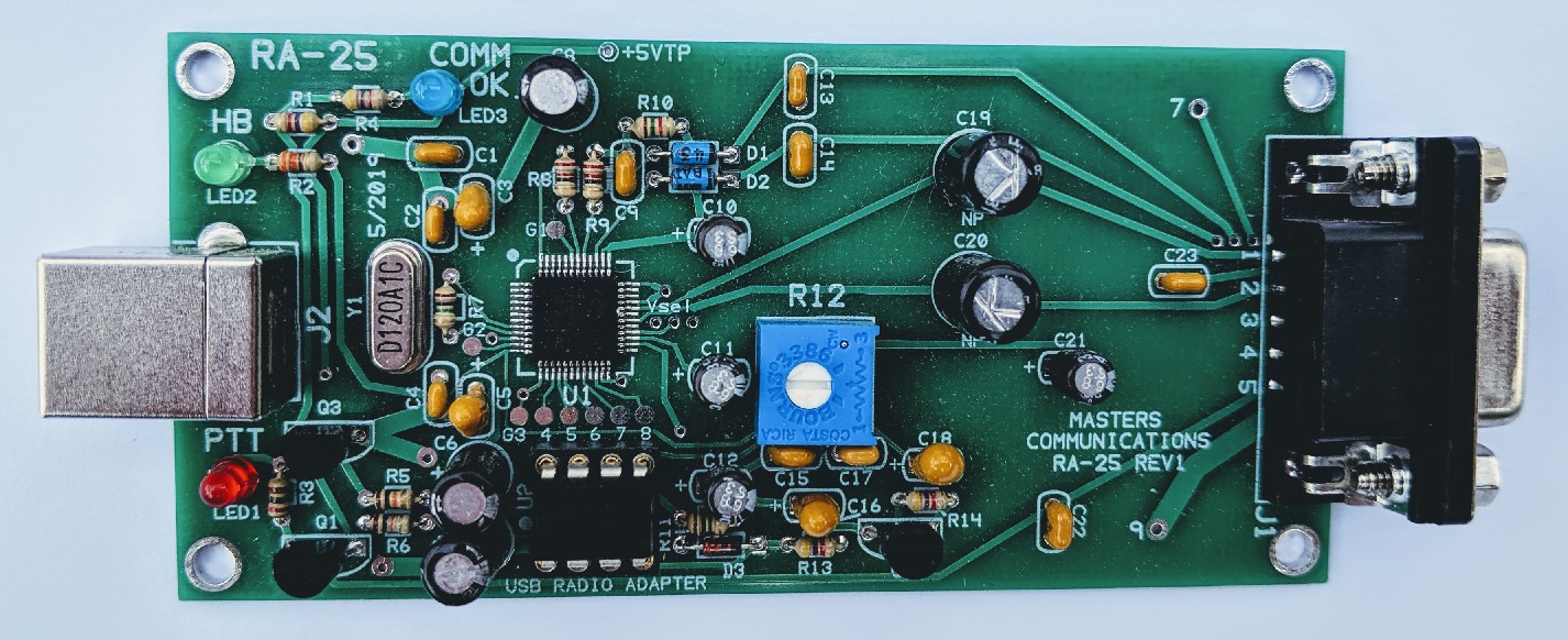
Top photo of the RA-25 PC board (click for a larger view).
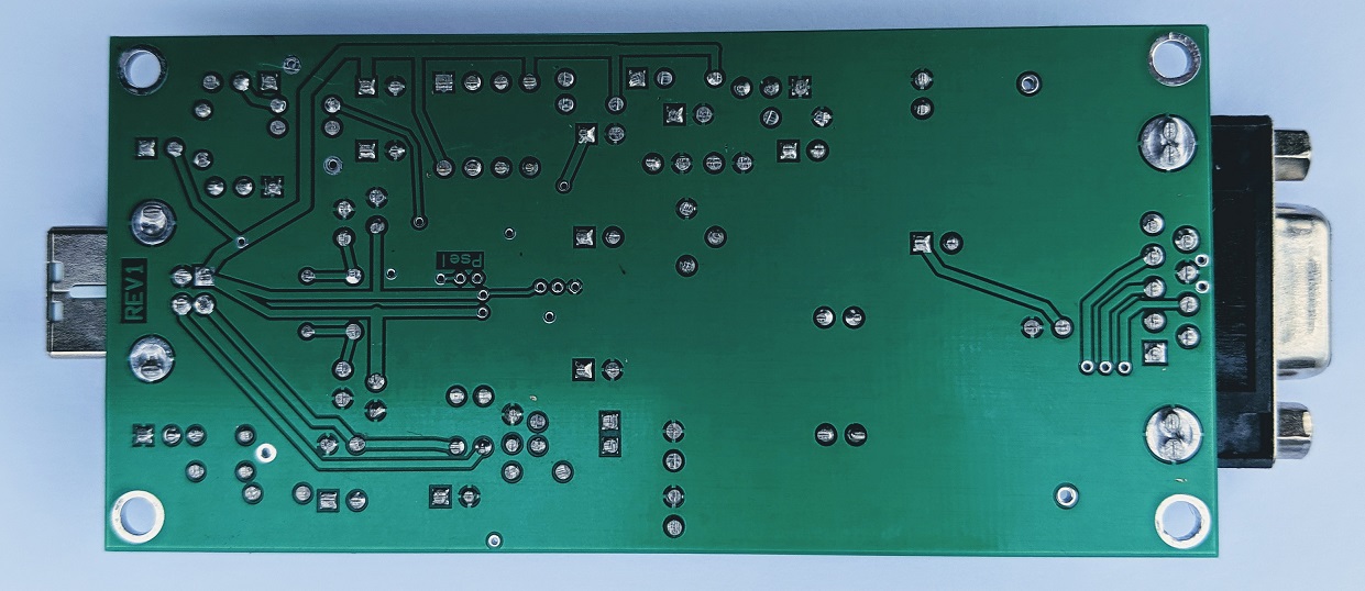
Bottom photo of the RA-25 PC board (click for a larger view).
Assembly:
If you purchased our kit, refer to the parts list and make sure you have all of the components
you need to build the kit. All of the components are supplied with the kit, and while we make
every effort to be sure we didn't omit any components, it can happen. If you are missing
anything, or ruin something, just contact us.
Click here for Parts List.
Assembly can be done by personal choice, but you may find it easier to install the shortest components first, building toward the tallest, and finish with the connectors on the ends. Except where noted - all parts are seated down against the board.
Install all resistors. Some resistors color bands may be hard to make out. If in doubt, use an ohm meter to verify the value before soldering it in place.
Install the diodes and shortest capacitors, observing polarity on all diodes and the polarized capacitors! The square pads are the banded end of the diodes and the + of the electrolytic capacitors. Small capacitors are identified as follows: "47" = 47pF, "103" = 0.01uF, "104" = 0.1uF, in other words the first two digits are the value and the third digit (if present) is the number of zeros you add to determine the value. In addition, there are two components that you need to make sure you install correctly as they are polarized and installed opposite from one another - C3 and C5. What might throw you are the wide traces. There are two wide traces going to C3, BUT only one going to C5, and it is ground. The positives of the capacitors face one another - in other words, they go toward the center of the board. It's helpful to look at the photo above.
Install the crystal.
Then, install the 3 LEDs (short lead to the square hole). If you have a metal case, install the USB connector now and use the front panel as an alingment guide to position the LEDs up off of the board the correct amount. This will insure the LEDs will stick through the holes when the board is placed into the rails of the metal case body.
Install the IC socket, and potentiometer.
Next, install the transistors (flat to flat on silkscreen). These will sit up off of the board surface by 1/4" or so.
Next, install the larger capacitors. If necessary, bend the leads of these straight so they sit down against the board.
Then, finish by installing the DB9F and USB "B" socket connector.
Information on the CM119A.
Click here
to download a manual for the C-Media CM119A.
Email
Kevin Custer for support.
Custom cables available from URI Cables. They will build a custom cable for the RA-25 for many radios.
Product of Masters Communications, all rights reserved.
Specifications may change without notice.
Images property of Kevin Custer - Masters Communications.
Board layout by Kevin Custer - W3KKC
HTML May 20, 2019, W3KKC All Rights Reserved!