Custom Products from Masters Communications

|
Custom Products from Masters Communications |
|
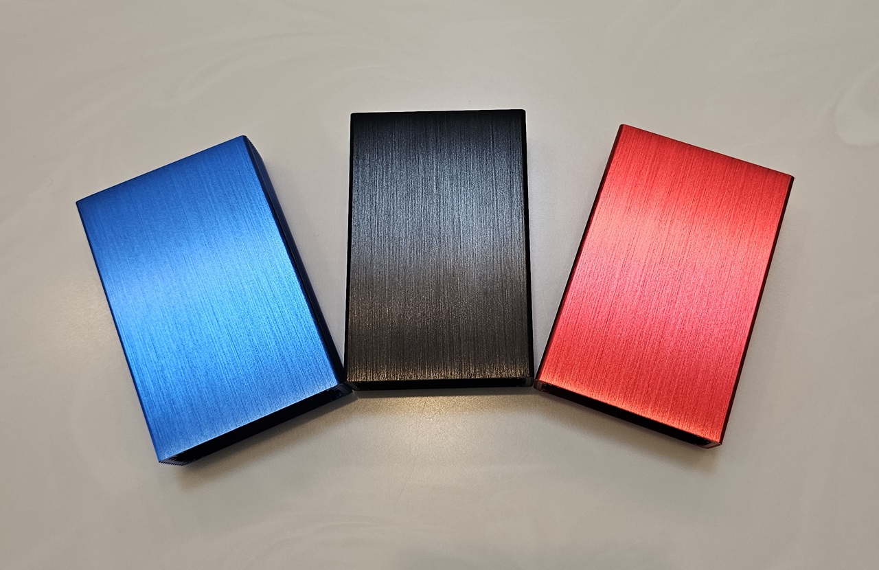
Available in
Blue, Black or Red box color.
All Metal - Secure Construction Case
Options to fit all radio connector types:
Blue, Black or Red body - black end panels with white lettering.
All hardware is provided!
Mini-DIN-6 / RJ45
DB9
Limited Time - Introductory Price = $30.00 each - any color.
Shipping and handling is calculated at checkout for US and International orders.
First-Class shipping available to most locations worldwide, calculated at checkout.
PayPal accepted - order below.
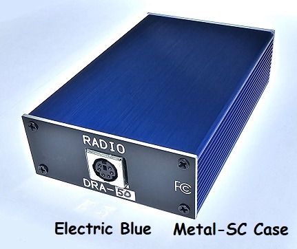
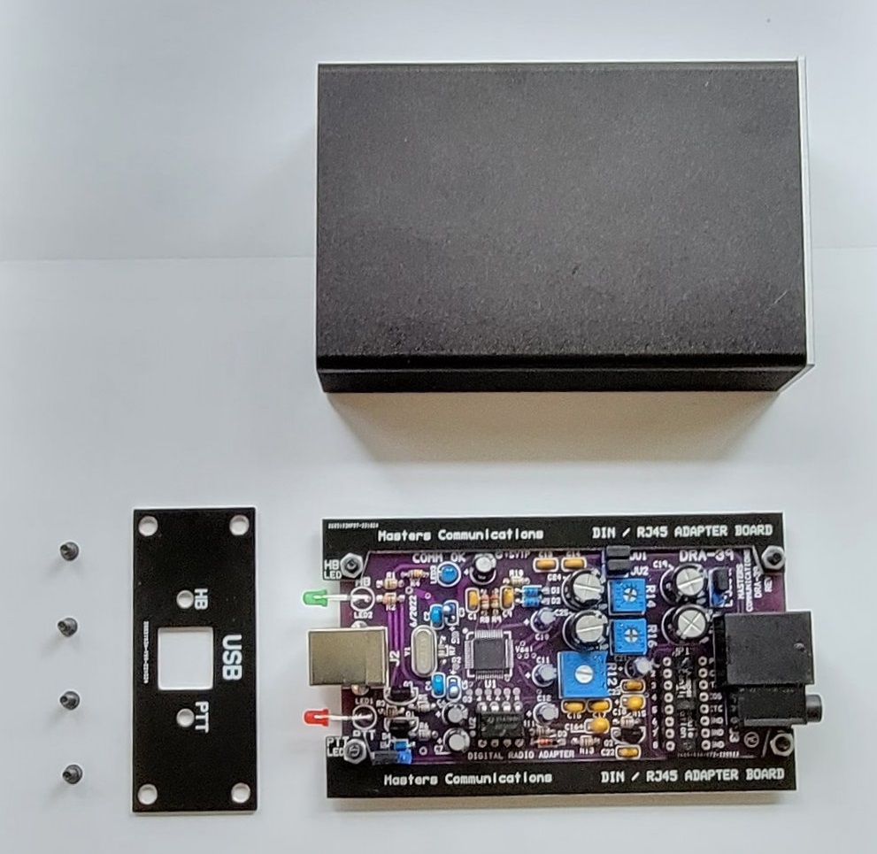
General Description:
The Metal-SC Case is a high-quality extruded aluminum case with a blue, black or red anodized finish that accommodates
all of the Standard RA or DRA Series radio interfaces. Custom black aluminum end panels
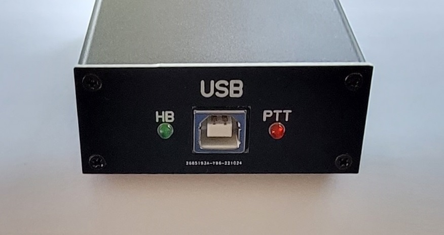
fit over the "USB" and "RADIO" connectors on each end. The USB end panel also has two holes for the
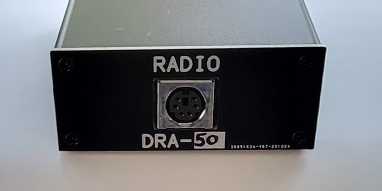
Green "HB" and Red "PTT" LEDs. The "RADIO" end panels accommodate the MINI-DIN-6 and RJ45 or DB9 radio
connectors. The rails and "RADIO" end panels are different for the DB9 boards - as compared to the
DIN/RJ45 boards. Radio interfaces that have a RJ45 or DIN6 radio connector take/use the same rails and end
panels. In other words - the DIN6/RJ45 design is universal and fit both the RJ45 and Mini-DIN-6 equipped radio
interfaces.
The Green and Red LEDs are (re)installed so that they stick through the "USB" end panel in the holes labeled "HB" and "PTT". Because of mechanical limitations the Blue LED is not brought to an outer surface. Instead - the Blue LED is installed normally against the board. One can assume that if the Green LED is flashing - the Blue LED is solidly lit. Since you'd need to open the case for troubleshooting - you'll be able to view all of the LEDs - including the blue one.
USB & LED End
DIN RADIO Connector End - marked for DRA-50
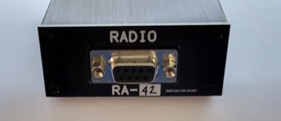
DB9 RADIO Connector End - marked for RA-42
The "D" can be covered with permanent marker for "RA Boards"
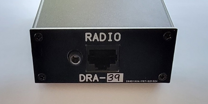
DRA-39 RADIO Connector End with SPKR Jack
The RADIO end panel has a silkscreen "box" to write the model number on with a thin permanent marker.
The "D" can be covered with permanent marker for "RA Boards".
DRA-39 Notes:
The DRA-39 is supplied with a different "RADIO" end panel that has an additional hole for the SPKR jack.
RA-38 and RA-42 Notes:
There is no accommodation for externally viewing the fourth "Yellow" LED on the RA-38 and RA-42.
Assembly Instructions:
Rail Installation -
The "HB" rail (upper rail) is installed so the inner edge of the rail board just passes by
the outer edge of the radio adapter board. These boards only overlap at the ends where
the screws are. When aligned - tighten the screws. You should be able to flex the adapter rail past
or beside the radio adapter circuit board. The "PTT" rail (lower rail) is installed and aligned
so the adapter rails fit into the slots of the case and give a slight amount of resistance.
In other words - a nice and easy but just snug fit. This adjustment can take a little trial
and error (leaving the screws a little loose) to get it right. When aligned - fully tighten the screws.
Install the USB / LED end panel. Start all four screws before doing a final tightening.
LED Mounting -
Mount the rails onto the board fisrt - as above. The LED leads are individually formed "one over
the other" observing polarity, offset, and lead spacing. Use the USB / LED end panel (and case) to align
the LEDs prior to soldering in place. The length of the leads may need to be trimmed so they
don't catch when sliding the board into position to check fit. The Green LED goes into the "HB" hole and
the Red LED goes into the "PTT" hole. It can be beneficial to tack solder one lead in-place and
reheat and adjust the position until both LEDs fit nicely through their respective holes in the end panel.
After you're satisfied with the alignment, solder both leads firmly.
Install the RADIO connector end panel. Start all four screws before doing a final tightening.
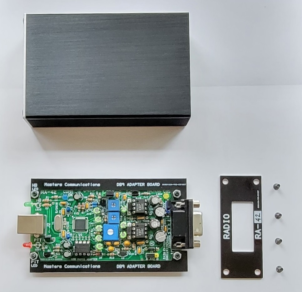
DB9 Rails attached to a RA-42
Secure Online Ordering - Use down arrow to make a choice that matches the radio connector type on
your RA/DRA.
Quantity can be changed after pressing the "Add to Cart" button.
Blue, Black or Red Metal-SC Case
for DB9 Radio Connector
for Mini-DIN-6 or RJ45 Radio Connector
Shipping amount is calculated at checkout for shipping to most locations Worldwide.
Email Kevin Custer for ordering information, ordering by check, and/or support of this exciting product.
Product of Masters Communications, all rights reserved.
Specifications may change without notice.
Images are property of Kevin Custer - W3KKC
Concept of Scott Currie NS7C and Kevin Custer W3KKC
HTML November 13, 2022, W3KKC All Rights Reserved!