Custom Products for the Digital Radio Amateur Enthusiast

|
Custom Products for the Digital Radio Amateur Enthusiast |
|
While this article is written mainly for VARA - it can be used generically for any application.
By Kevin Custer W3KKC
Please read through the entire procedure at least once before performing audio calibration!
Background -
VARA's Auto-Tune assumes the person you're connecting to has set up their equipment
perfectly. It will calibrate correctly as long as this assumption is correct.
If no one that you're attempting to connect to has actually calibrated correctly, everyone ends up chasing each others tail - so to speak. Where audio levels are concerned, until someone has properly calibrated their station that others can calibrate to, a lot of time gets wasted because the levels required for a different station can be vastly different. While VARA allows for a pretty wide range of levels, things work better if the level requirements are the same for all stations communicating with each other, and these levels are the correct amount. Exact isn't necessary, close works well, even for multiple stations.
Overview:
It's best to use a FM Communications Service Monitor, SDR, or
FM Deviation Meter to properly set the transmit audio level
(modulation / deviation) used for digital data communications. For FM digital data, a deviation level
of 2 to 3 kHz is generally good, with 2.25 kHz being perfect. However, access to one of these pieces
of equipment may be difficult (or impossible) in your area. This article attempts to provide a
method of setting levels that gets you "in the ball park". If you want to obtain a piece of equipment
at an affordable price, look at the link above or at the bottom of the page for our FMDM-150M deviation
meter.
Setting the receive level:
The larger pot (R12) controls the RX level. In VARA, adjust the RX level control to achieve
a -10 or -11 dBFS reading on the V/U meter with just noise on the channel (no one transmitting
- squelch open).
Setting the transmit level:
There are at least three ways to adjust the transmit level. All of them are acceptable and may
require a combination of them to achieve the correct level:
1 - Mechanical rotation of R14 / R16. Remember, on a DRA-100, R14 is the front panel mounted TX control.
2 - Windows Speaker (volume) level.
3 - The TX level in the VARA software.
NOTE: There are no differences between the Left and Right TX channels of all DRA's - the audio level capability is the same for both channels. All of our products are wired logically for potentiometer rotation. If the software is telling you to turn R14 CCW, that means a reduction in level. Conversely - if the software is telling you to turn the control CW, that's an increase in level. On a DRA-100, the right channel is the main or primary channel because its level control is the front panel mounted TX pot.
VARA can lie to you telling you to increase the transmit audio level when it's already way too high. Start out low - and carefully adjust higher.
Additionally - Some radios, including portables, may have a menu setting for TX drive level. You may be able to reduce or increase the TX level by some software/menu adjustment of the microphone level in the radio, but this is likely unnecessary when using the combination above.
It's beneficial to listen to another radio (on channel) to get an understanding of how much data audio is being transmitted. For FM - a hand-held radio usually works well for this. The rotation of the smaller TX pot(s) should provide a smooth - wide ranging adjustment. If the pot is all "one ended" and you go from nothing to overdrive in a few degrees of rotation from the full (CCW) setting of the pot, then reduce the Windows speaker level until the rotation provides a nice smooth range. It doesn't hurt anything to have the TX pot(s) barely cracked open to maximize the reduction of level for radios that are sensitive on their modulator or MIC inputs, but it's best to reduce the Windows Speaker level so setting the rotational value is easier. It's not necessary to achieve a centered TX pot rotational value.
NOTE: When setting the transmit level - be mindful of the volume level on the monitor radio. If you start out with a volume level that's too high, you may run into distortion. You need to maintain a volume level on the monitor radio that allows you to observe when the transmit data/tone level stops increasing or becomes distorted. If the volume level on the monitor radio is set too high, you may hear distortion and falsely accuse the transmitting radio. Distortion caused by overdrive in the monitor radio must be avoided. Otherwise, proper levels won't be achieved.
Procedure for setting TX audio level:
Initially - set the TX level control to minimum (CCW). Start by sending data or a test tone using
the application you're going to operate with. While listening "on-frequency"
with a different (monitor) radio, note the volume level coming out of its speaker. Again, a portable
works well for this. If this is VARA or any other program that uses Hardware PTT, it's possible
(at least with a DRA) to key the transmitter and have no audio on the transmitter with the control
fully CCW. Continue to send the test tone or data (multiple times if necessary) while slowly
and carefully rotating the TX level control up (CW) noting the volume of this signal on your monitor
radio. Continue rotating until you perceive no more increase in volume level or when if the sound of
transmission changes because of distortion. Then turn the control down a good bit until you
hear a noticeable reduction in volume on the monitoring radio.
Another way...
You should hear 10 distinctly different audio levels from
a monitor radio when doing a VARA FM "Auto Tune" as the auto tune sequence progresses through its steps.
The key is to make as many different levels available to the other station as possible. Start with a lower
(counter-clockwise) position of R14 (or R16) and increase it until you just hear it. Then - set the
level control to a position that allows you to obtain as many distinctly different levels as possible,
with the last one (#10) sounding the same level as the one before it (#9). If the transmit
level is set too high, you may not hear a change in level as the steps progress, or you may only
hear a few differnet levels and the last ones all sound the same. The more level choices you give
your VARA partner - the better chance they'll like one of them.
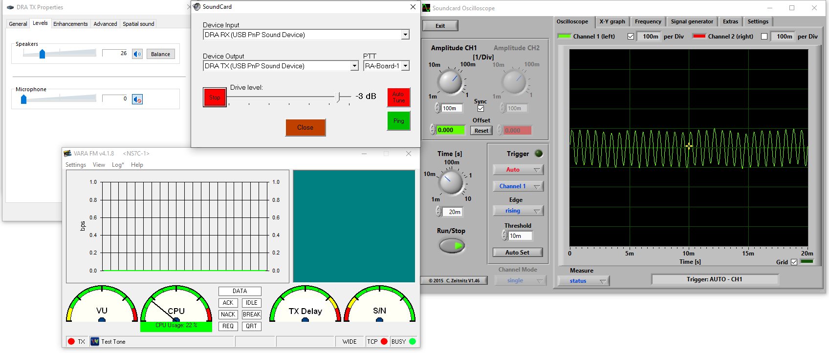
Using additional (free) tools:
If you download a PC based oscilloscope application like
Soundcard Oscilloscope, you can
acoustically couple the monitor radio speaker to a computer microphone and actually see (and read) the
level on the screen. If we assume that limiting occurs in most radios at 4.5kHz, a 50% reduction in signal
results in approximately 2.25kHz deviation which is prefect for VARA FM. Packet usually works better with
a little more deviation - like 3 to 3.5 kHz, or around 70% of the level at which limiting occurs.
This adjustment method uses the procedure above, you're just using the oscilloscope to see (instead of your ears to hear) the threshold where limiting (or distortion) occurs. You adjust the audio level to the threshold of limiting, read that amount as a value on the screen, and reduce it to a level which yields the suggested amount. Modulation is usually very linear so doing the math is easy - multiply the threshold value by .5 (that's point five) for VARA FM, or .7 (that's point seven) for Packet. Obviously, acoustic coupling requires a fairly quiet environment, otherwise, you'll additionally see the undesired noise of the surroundings. You can mitigate ambient noise and get more accurate readings by physically cabling the speaker output to the microphone or line input of the sound card in the computer - - but, this often unnecessary. Refer to the image below for an example of this method.
An affordable professional way to set transmit deviation:
The Masters Communications FMDM-150M Deviation Meter
Don't be tempted to readjust the RX level after achieving -10 or -11 on the RX V/U Meter with open squelch noise. After others have calibrated, the RX level on the V/U meter will show a data level of just under 12:00 noon when receiving a properly deviated data transmission.
This method is not perfect, but it attempts to keep the TX signal from becoming limited or distorted (or totally muted) by the transmitters audio processing.
Hope this helps... Kevin W3KKC
Email Kevin Custer for additional support.
Text additions and image courtesy of Scott Currie NS7C
Article by Kevin K. Custer W3KKC
HTML February 4, 2022, All Rights Reserved - W3KKC.