Custom Products for the Digital Radio Amateur Enthusiast

|
Custom Products for the Digital Radio Amateur Enthusiast |
|
By Kevin Custer W3KKC
Background -
Barry Feierman K3EUI wrote an article that appeared in the April 2022 issue of QST magazine. That
article explains how it's possible to connect an inexpensive HT to an appropriate sound card and use it for
Winlink using VARA FM Narrow. Barry used a DRA-SR-RJ45 sound card and a SLCABHTW cable. This cable is
available from Tigertronics or an authorized dealer. It's specifically designed to connect several HT's
to a SignaLink® USB. This cable requires a SLMOD6PM Plug & Play jumper module, or you can follow the
jumper arrangement supplied with the cable or the one shown below. This cable and module also works
with the Masters Communications DRA-39, DRA-SR-RJ45 and DRA-100-RJ45, or even the new RA-38.
The DRA-39 is a inexpensive solution and is very simple to connect up bacause of these pre-made radio cables and jumper modules, as mentioned above. HT's don't require the elevated audio of the amplified DRA's. While a DRA-45 - '50 or other LM386 equipped DRA would work, if you're going to buy an interface specifically for an HT, the DRA-30, and '39 are probably the best choices, with the DRA-39 being preferred because of the availability of pre-made Radio Cables & Plug & Play jumper modules. These are available from Tigertronics or an authorized SignaLink™ dealer. They have cables and modules for several models and manufacturers of portable radios (HT's).
But what about using other DRA's? - - Yes - they work too!
In my testing, I confirmed that the DRA-30, '34, '36, and '39 work identically well with my Baofeng UV-5R.
Connection of a DRA-39, DRA-SR-RJ45 or DRA-100-RJ45:
Photo of the Dual TRS connector.
Part of the Tigertronics SLCABHTW cable.
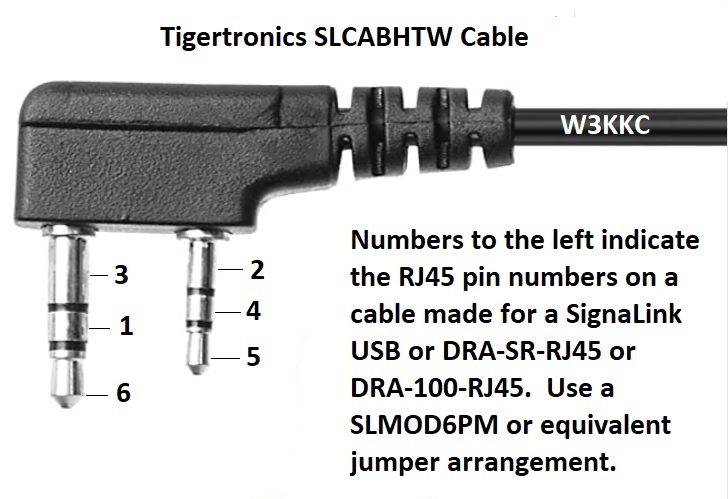
Male RJ45 plug pinout:
1 = RED = MIC (transmit audio)
2 = BLACK = Ground
3 = BLUE = PTT
4 = WHITE = N/C *
5 = GREEN = Speaker (receive audio)
6 = ORANGE = N/C *
7 = N/C
8 = N/C
N/C means No Connection.
* NOTE: The White and Orange wires in the cable are not used. These wires are intentionally not routed via the configuration socket.
Configuration Socket Wiring:
Refer to the image below or the yellow paper supplied with the SLCABHTW cable to see why.
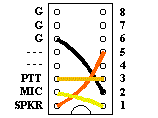
TX audio attenuator: The DRA-SR and DRA-100 Series have audio attenuators that can be enabled by removing a mechanical jumper (no soldering required). For HT's, we recommend enabling the transmit (TX) attenuator. This is accomplished buy removing the jumper (short) on JU9 on either unit. Doing so allows the TX audio level to be more easily adjusted - as the control isn't all "one ended" (has limited rotational range).
It's strongly recommended that you use an external antenna on the HT, as RFI can crash the computer.
Connection of a DRA-30.
Using a RJ45-6 Adapter, we connect the
SignaLink SLCABHTW cable to a DRA-30 by configuring the adapter as follows by pressing the pins into
the back end of the DB9 male connector until each one snaps into place.
1 - Blue
2 - Yellow
3 - Black
4 - Red
5 - Green
6 - Orange
7 - White
8 - Nothing
9 - Gray
NOTE: Arranging the pinout as above insures that the Orange and White wires in the SLCABHTW cable are
NOT routed anywhere.
If these wires are connected or have continuity to anything, undesired operation, including unintentional
PTT, will occur.
Make sure JU1 and JU2 on the DRA-30 are removed.
Attach the RJ45-6 Adapter to the DRA-30 using the supplied thumb screws. Then put the RJ45 male connector into the socket on the RJ45-6 adapter. Make sure JU1 and JU2 on the DRA-30 are removed. Set the squelch setting to "0" (zero) for wide open squelch noise. Set the audio levels properly, and begin using the set-up.
It's strongly recommended that you use an external antenna on the HT, as RFI can crash the computer.
Connection of a DRA-36 (or any DRA with a Mini-DIN-6 radio connector):
We connect the SignaLink SLCABHTW radio cable to a DRA-36 by cutting off the RJ45 connector and soldering a male
Mini-DIN-6 connector to the cable as follows. See image below for pin assignments shown correctly for soldering
the connections.
1 - RED - Transmit Audio
2 - BLACK - Ground - GND
3 - BLUE - PTT
4 - WHITE - N/C
5 - GREEN - RX Audio (DATA OUT 1200)
6 - ORANGE - N/C
N/C means No Connection.
NOTE: The Orange and White wires in the cable are left unconnected. Cut / Tape them off so they don't
short out to each other or another connection.
If these wires are connected or have continuity to anything,
undesired operation, including unintentional PTT, will occur.
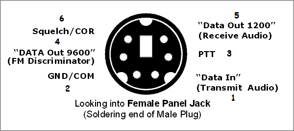
Attach the cable to the DRA-36 and radio. Make sure JU1 and JU2 on the DRA-36 are removed. Set the RX Baud Jumper (JU5) on the DRA-36 to the "A" or 1200 position. Set the squelch setting to "0" (zero) for wide open squelch noise. Set the audio levels properly, and begin using the set-up.
It's strongly recommended that you use an external antenna on the HT, as RFI can crash the computer.
Email Kevin Custer for additional support.