Custom Products for the Digital Radio Amateur Enthusiast

|
Custom Products for the Digital Radio Amateur Enthusiast |
|
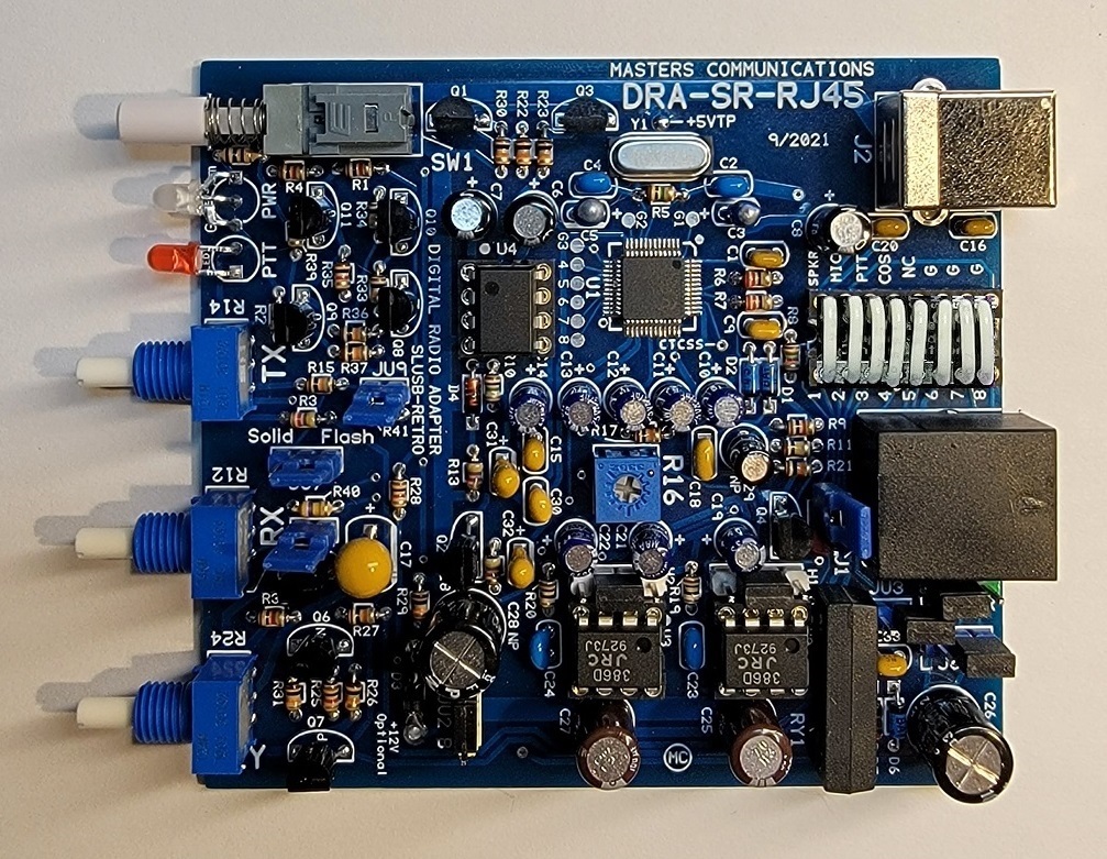
Top photo of the DRA-SR-RJ45 circuit board (click for a larger view).
Shown with configuration socket jumpered "straight across" with supplied wires.
REV1 (blue board) Parts List:
If you purchased our kit, refer to the parts list and make sure you have all of the components
you need to build it.
Click here
for REV1 Parts List.
REV2 (green board) Parts List:
Click here
for REV2 Parts List.
NOTE: - The parts list includes several construction notes too! Be sure to reference it along with this article to minimize the possibility of construction mistakes.
Please read through this article and the parts list at least once before starting your assembly. It will bring your attention to things that need to be done in order to prevent assembly errors.
Assembly can be done by personal choice, but you may find it easier to build in a vertical height order - installing the shortest components first, building toward the tallest, and finish with the connectors on the ends. The LEDs will need to have their leads bent similarly to the way they are on your original board so they will fit into their holes and mount properly. With the exception of the LEDs, all other components are installed tight against the circuit board.
Install all resistors. Some resistors color bands may be hard to make out. If in doubt, use an ohm meter to verify the value before soldering it in place. Bend both of the resistor leads sharply at the body at a 90 degree angle.
Install the crystal - tight against the board. Use the supplied plastic spacer under the crystal to insulate the metal body from the traces under it.
Install the diodes and shortest capacitors, observing polarity on all diodes and the polarized capacitors! The square pads are the banded end of the diodes and the + of the electrolytic capacitors. Small capacitors are identified as follows: "47" or "470" = 47pF, "103" = 0.01uF, "104" = 0.1uF, "105" = 1uF, and "107" = 100uF. In other words the first two digits are the value and the third digit (if present) is the number of zeros you add to determine the final value.
There are five Tantalum capacitors that are polarized and need to be installed the correctly. This circuit board has silkscreened outlines for the Tantalum capacitors that were altered to make the installation easier. The outlines of these components look like an oval race track. One of the longer straight lines is printed heavier (wider). The Tantalum capacitor is inserted so the printing on the capacitor is on the same side as the wider line. Look at C5 near the crystal in the photo above for an example. Notice C3 and C5 install in opposite directions from one another. Do NOT install the 100uF Tantalum at this time, as it's quite a bit taller.
Install the IC sockets - match the notch to the silkscreen.
Next, install the transistors (flat to flat on silkscreen). The silkscreen has a letter inside the outline of the part. The N stands for NPN (2N2222), and P for PNP (2N2907). F stands for FET (2N7000) and D stands for Darlington (MPSA13).
Install the two, three and four pin headers - observing their colors and positions as noted on the parts list.
Install the relay. It doesn't really matter which way it's oriented, but it looks better if the printing is toward D5 so you can read it.
Install the 8-pin ICs - 2 - LM386s and 1 - LM555 observing correct orientation. Match the dot on the IC to the notch end of the socket.
Next, install the larger capacitors. You may need to bend the leads of these straight so they sit down tight against the board.
Install all potentimeters. Make sure they are tight against the board. The panel mounted pots have a anti-rotation "pin" that sticks out near the shaft threads. If I've forgotten, these need to be cut off of each pot. Look at the pots on the original SignaLink board for reference, as these were cut off at the factory. These are easily removed with sharp side cutters.
Install the 100uF Tantalum capacitor.
Then, install the 2 LEDs. NOTE the flat on the LEDs lens and the circuit board outline to insure the correct orientation of the LEDs. The LEDs will need to have their leads pre-bent similarly to the way they are on your original board so they will fit into their holes and mount properly through the panel. A pair of needle nose pliers with thin jaws work well for this. Use your front panel to get the alignment right while soldering them in place.
Then, finish by installing the RJ45, USB "B", and SJ1 socket connectors.
Put the jumper shorts over the headers per the DRA-SR-RJ45 jumper document.
Install the white jumper wires in the configuration socket as required or an optional SignaLink "plug-&-play" module - sold elsewhere.
Put the board into your SignaLink case. REV2 models include a new 3D printed rear panel with 1/8" speaker jack - feel free to use it, or not! Refer to the case instructions for additional help.
Information on the CM119A.
Click here
to download a manual for the C-Media CM119A.
Email
Kevin Custer for support.
Product of Masters Communications, all rights reserved.
SignaLink® and SignaLink USB® are registered trademarks of
Tigertronics.
The use of the name SignaLink and/or SignaLink USB is only in reference to this product.
No infringement for such use is intended.
Specifications may change without notice.
Images property of Kevin Custer - Masters Communications.
Board layout by Kevin Custer - W3KKC
HTML June 24, 2021, W3KKC All Rights Reserved!