Custom Products for the Digital Radio Amateur Enthusiast

|
Custom Products for the Digital Radio Amateur Enthusiast |
|
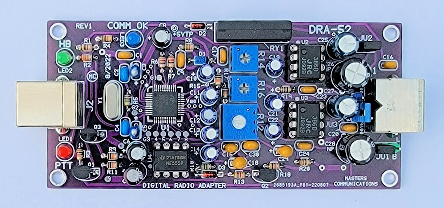
Top photo of the DRA-52 circuit board (click for a larger view).
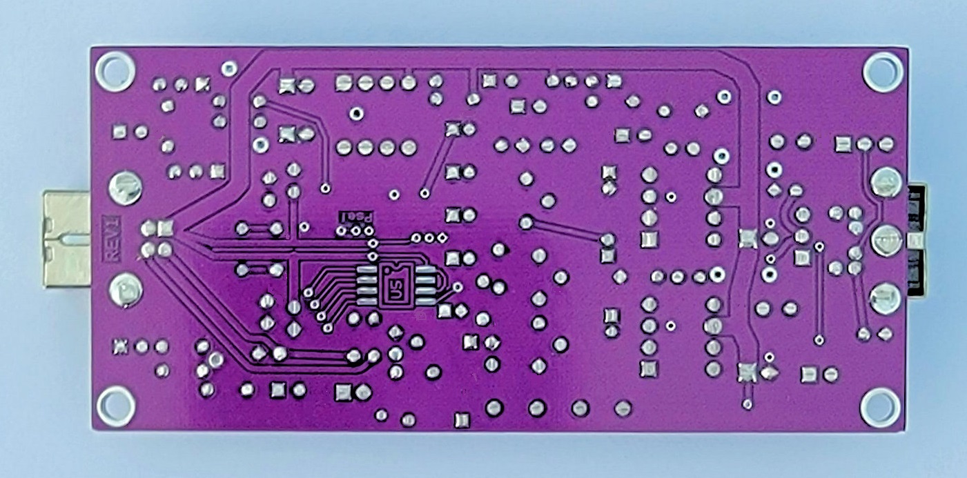
Bottom photo of the DRA-52 circuit board (click for a larger view).
Assembly:
If you purchased our kit, refer to the parts list and make sure you have all of the components
you need to build the kit. All of the components are supplied with the kit, and while we make
every effort to be sure we didn't omit any components, it can happen. If you are missing anything,
or ruin something, just contact us.
Click here for Parts List.
Assembly can be done by personal choice, but you may find it easier to install the shortest components first, building toward the tallest, and finish with the connectors on the ends.
Install all diodes and resistors. Some resistors color bands may be hard to make out. If in doubt, use an ohm meter to verify the value before soldering it in place. The square pads are the banded end of the diodes.
Install the crystal.
Install the shortest capacitors. Small capacitors are not polarized and can be inserted either way. They are identified as follows: "47" or "470" = 47pF, "103" = 0.01uF, "104" = 0.1uF, "105" = 1uF. In other words the first two digits are the leading value and the third digit (if present) is the number of zeros you add to determine the final value.
All Tantalum capacitors install into locations that have silkscreen markings that make orientation easy. There are four Tantalum capacitors that are polarized and need to be installed the correctly. This circuit board has silkscreened outlines for the Tantalum capacitors that were altered to make the installation easier. The outlines of these components look like an oval race track. One of the longer straight lines is printed heavier (wider). The Tantalum capacitor is inserted so the printing on the capacitor is on the same side as the wider line. Look at the outline for C5 (near the crystal) in the photo above for an example. NOTE: C3 and C5 install in opposite directions from one another.
Then, install the 3 LEDs (short lead to the square hole)
Note: This is different from the polarized capacitors!
Install the IC sockets, and potentiometers.
Install the relay. It doesn't really matter which way it's oriented, but it looks better if the printing is outward so you can read it.
Next, install the transistors (flat to flat on silkscreen).
Install the two and three pin headers.
Install the largest polarized capacitors - observing polarity! The square pads are the long leads (+ of the electrolytic capacitors). Note: This is different from the LEDs! Where necessary, bend the leads of these straight so they sit down against the board.
Then, finish by installing the Mini-DIN-6 and USB "B" socket connectors.
Put the jumpers onto the headers as per the jumper document, and install the three 8 pin ICs in their proper locations - Yes, it matters where the IC's are placed!
Information on the CM119A.
Click here
to download a manual for the C-Media CM119A.
Email
Kevin Custer for support.
DRAC-12 - 6-foot Mini-DIN-6 Radio Cable can be added optionally to connect several data capble radios to the DRA-52.
Product of Masters Communications, all rights reserved.
Specifications may change without notice.
Images property of Kevin Custer - Masters Communications.
Board layout by Kevin Custer - W3KKC
HTML August 13, 2022, W3KKC All Rights Reserved!