Custom Products for the Digital Radio Amateur Enthusiast

|
Custom Products for the Digital Radio Amateur Enthusiast |
|
Product Support Documentation
Model DRA-39
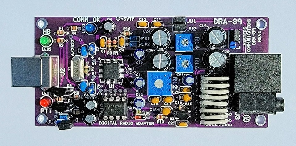
Top side of DRA-39 circuit board - shown slightly enlarged.
(Click photo to show a larger image)
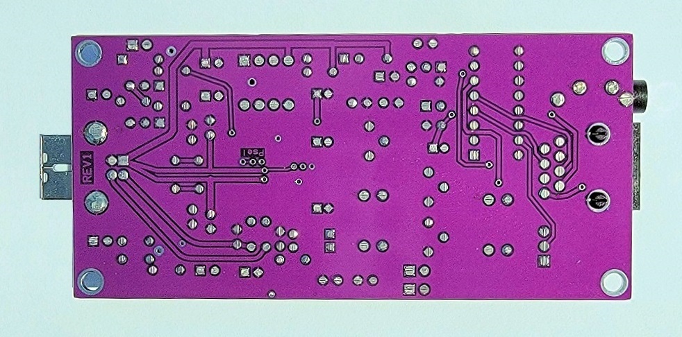
Bottom side of DRA-39 circuit board - shown slightly enlarged.
(Click photo to show a larger image)
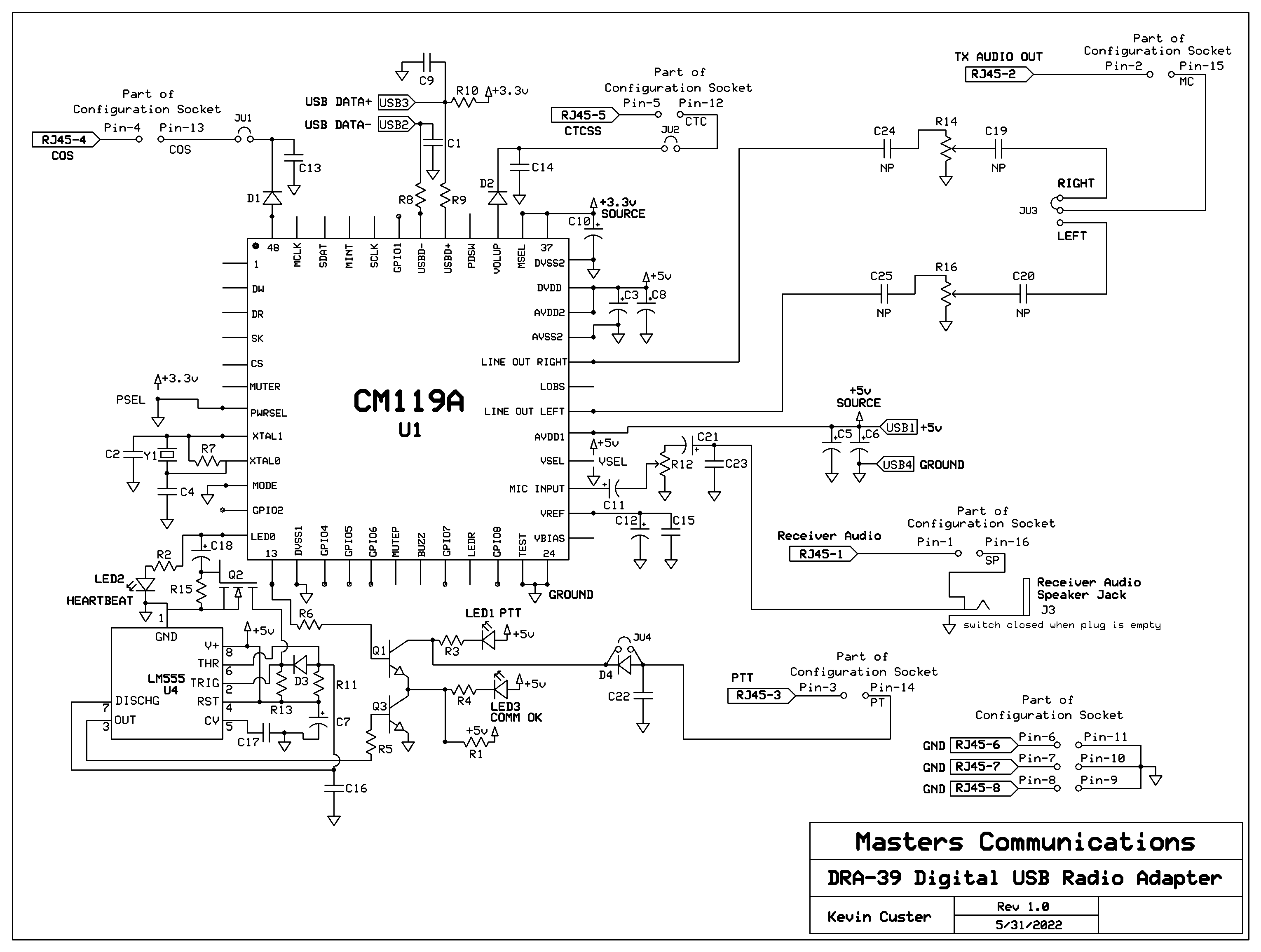
Schematic Image - Click to download a high quality PDF.
Overview of DRA-39
1, Use with VARA FM or other digital communications requiring a very high quality sound card.
2, Compatible with SignaLink USB radio and speaker cables, and Plug-&-Play jumper modules.
3, Kit comes with the surface-mount IC preinstalled.
Parts List:
If you purchased our kit, refer to the parts list and make sure you have all of the components
you need to build it.
Click here
for Parts List.
Assembly - Construction Article:
Click here for assembly instructions and construction notes - with large photos.
"JU" Jumper Settings:
Click here
for Jumper Settings and other board connection assignments.
RJ45 Pinout
Click here
for RJ45 Pinout.
Installation:
This device is intended to be installed inside a radio, computer, or plastic box for protection.
Refer to the schematic for the pinout of the RJ45 where all of the logic signals, power
connections, and audio signals are listed.
Recommended powering requirements:
The board is supplied with 5 VDC from the USB connection.
Recommended receive audio input level:
The DRA-39 accepts the widest range of audio compared to any other similar radio adapter. The
input signal is attenuated by a potentiometer, giving the broadest range of acceptable levels.
If your receiver audio level is adjustable or programmable,
we recommend around 2.0 volts P-P. This allows very good signal-to-noise
ratio and low cabling cross talk. This level results in a 50% rotational setting of the
potentiometer.
1/8" audio input jack:
Unlike most other DRA's, the DRA-39 has a 1/8" jack for receive audio. This is an input which can be
driven from the speaker jack on the radio - when required. This jack is switched, and when
no plug is inserted, audio is routed from pin 16 of the configuration socket to the input
of the board. Inserting a plug into the socket takes priority and disconnects audio
that appears at pin 16.
Optional Plastic Case:
A Plastic Case is available
optionally for the DRA-39. Available in several colors!
Which C-Media chipset is used?
All DRA series radio adapter boards are supplied with a Genuine C-Media CM119A.
The PC board was designed to be versatile. A CM108 and CM119 is also acceptable. There are slight differences between these components, and the board can be 'programmed' to accept any of the three.
Information on the CM119A.
Click here
to download a manual for the C-Media CM119A.
Secure PayPal ordering available from the DRA-39 main page.
Email Kevin
Custer for support of this
exciting product.
Product of Masters Communications, all rights reserved.
Specifications may change without notice.
Images property of Kevin Custer - W3KKC
Board layout by Kevin Custer - W3KKC.
HTML May 30, 2022, W3KKC All Rights Reserved!