Custom Products for the Digital Radio Amateur Enthusiast

|
Custom Products for the Digital Radio Amateur Enthusiast |
|
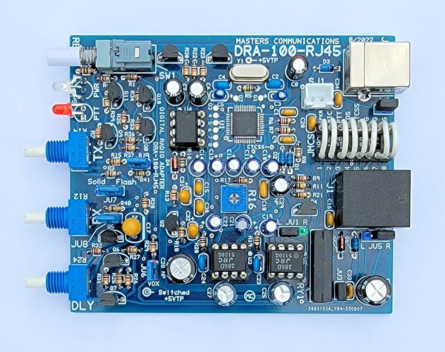
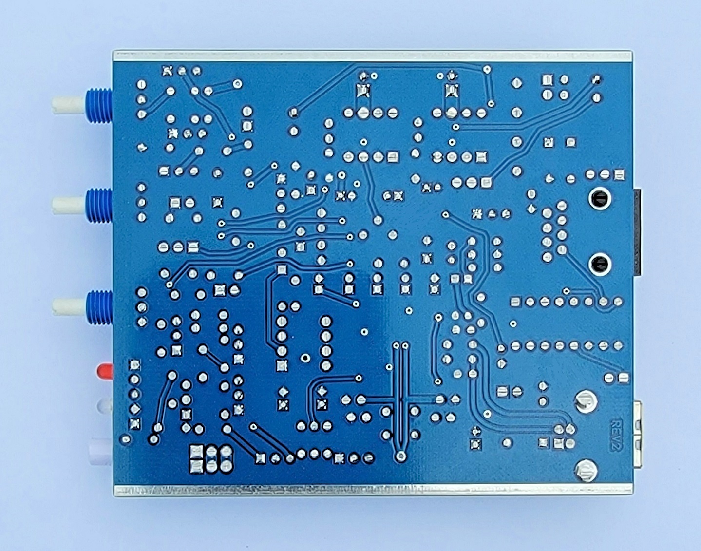
Top and Bottom photos of the DRA-100-RJ45 REV2 circuit board.
Click either image for a larger view.
Click here
for Parts List.
The parts list includes several construction notes too! Be sure to reference it
along with this article to minimize the possibility of construction mistakes.
Please read through this article and the parts list at least once before starting your assembly. It will bring your attention to things that need to be done in order to prevent assembly errors.
Assembly can be done by personal choice, but you may find it easier to build in a vertical height order - installing the shortest components first, building toward the tallest. The LEDs already have their leads bent for proper installation. With the exception of the LEDs, all other components are installed tight against the circuit board.
Install all resistors. Some resistors color bands may be hard to make out. If in doubt, use an ohm meter to verify the value before soldering it in place. Bend both of the resistor leads sharply at the body at a 90 degree angle.
Now - install the crystal - tight against the board. Use the supplied plastic spacer under the crystal to insulate the metal body from the traces under it.
Then - install the diodes observing polarity. The lead on the banded end goes in the square hole.
Install the shortest capacitors. Small capacitors are identified as follows: 22 or 220 = 22pF, "47" or "470" = 47pF, "103" = 0.01uF, 473 = .047uF, "104" = 0.1uF. In other words the first two digits are the value and the third digit (if present) is the number of zeros you add to determine the final value. These small capacitors are not polarized and can be installed either way.
There are five Tantalum capacitors. They look like a tear drop with leads. They are polarized
and need to be installed correctly. The circuit board has silkscreened outlines for the
Tantalum capacitors that were altered to make the installation easier. The outlines of these
components look like an oval race track. One of the longer straight lines is printed heavier
(wider). The Tantalum capacitor is inserted so the printing on the capacitor is on the same
side as the wider line. Look at the outline for C17 (the large yellow Tantalum) in the photo
above for an example. Notice C3 and C5 install in opposite directions from one another. Go ahead
and install these now.
NOTE: Do NOT install the 100uF Tantalum (marked 107) at this time, as it's quite a bit
taller, and will be placed later in vertical order.
Now - install the 10k Trimpot in location R16.
Then - install the white rectangular MOLEX XH pin socket SJ1. Install it so the side with the cut-out goes toward C20.
Install the IC sockets - match the notch to the silkscreen.
Next, install the transistors (flat to flat on silkscreen). The silkscreen has a letter inside the
outline of the part.
The N stands for NPN (2N2222), and P for PNP (2N2907). F stands for FET (2N7000)
and D stands for Darlington (MPSA13).
Install the two and three pin headers - observing their colors and positions as noted on the parts list.
Now - install the relay. It doesn't really matter which way it's oriented, but it looks better if the printing is toward D5 so you can read it.
Then - install the 8-pin ICs - 2 - LM386s and 1 - LM555 observing correct orientation. Match the dot on the IC to the notch end of the socket.
Next - install the power switch. Its orientation is obvious.
Install the larger capacitors. You may need to bend the leads of these straight so they sit down tight against the board. The + of the polarized capacitors go into the holes with the square pad.
Now - install the 100uF Tantalum capacitor observing polarity. The printing goes on the side of the silkscreened outline that's printed wider.
Then, install the RJ45 and USB "B" socket connectors.
Install all shaft potentimeters. Make sure they are tight against the board, and pushed back into their holes (and away from the boards edge) while keeping the alignment straight.
Then, install the 2 LEDs. NOTE the flat on the LEDs lens and the circuit board outline to insure the correct orientation of the LEDs. The LEDs have their leads pre-bent so they will fit into their holes and mount properly through the panel. Temporarily place your front panel over the shafts of the pots and the button of the power switch to get the alignment right while soldering them in place.
Put the jumper wires into the configuration socket as necessary.
Put the jumper shorts over the headers per the DRA-100-RJ45 REV2 jumper document. Some of these jumpers have handles that may need trimmed to allow the board to slide into the case. Just trim the minimum amount of length necessary to allow for clearance.
Three small plastic washers are provided to space the body of the shaft pots slightly away from the front panel. One washer is placed onto the threaded body of each pot - - not now, in the next step.
Go to the article about installing the board into the case.
Email
Kevin Custer for support.
Product of Masters Communications, all rights reserved.
Specifications may change without notice.
Images property of Kevin Custer - Masters Communications.
Board layout by Kevin Custer - W3KKC
HTML Febryary 14 2022, W3KKC All Rights Reserved!