Custom Products for the Digital Radio Amateur Enthusiast

|
Custom Products for the Digital Radio Amateur Enthusiast |
|
Product Documentation
Model DRA-MIX-MUX
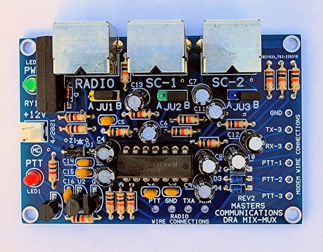
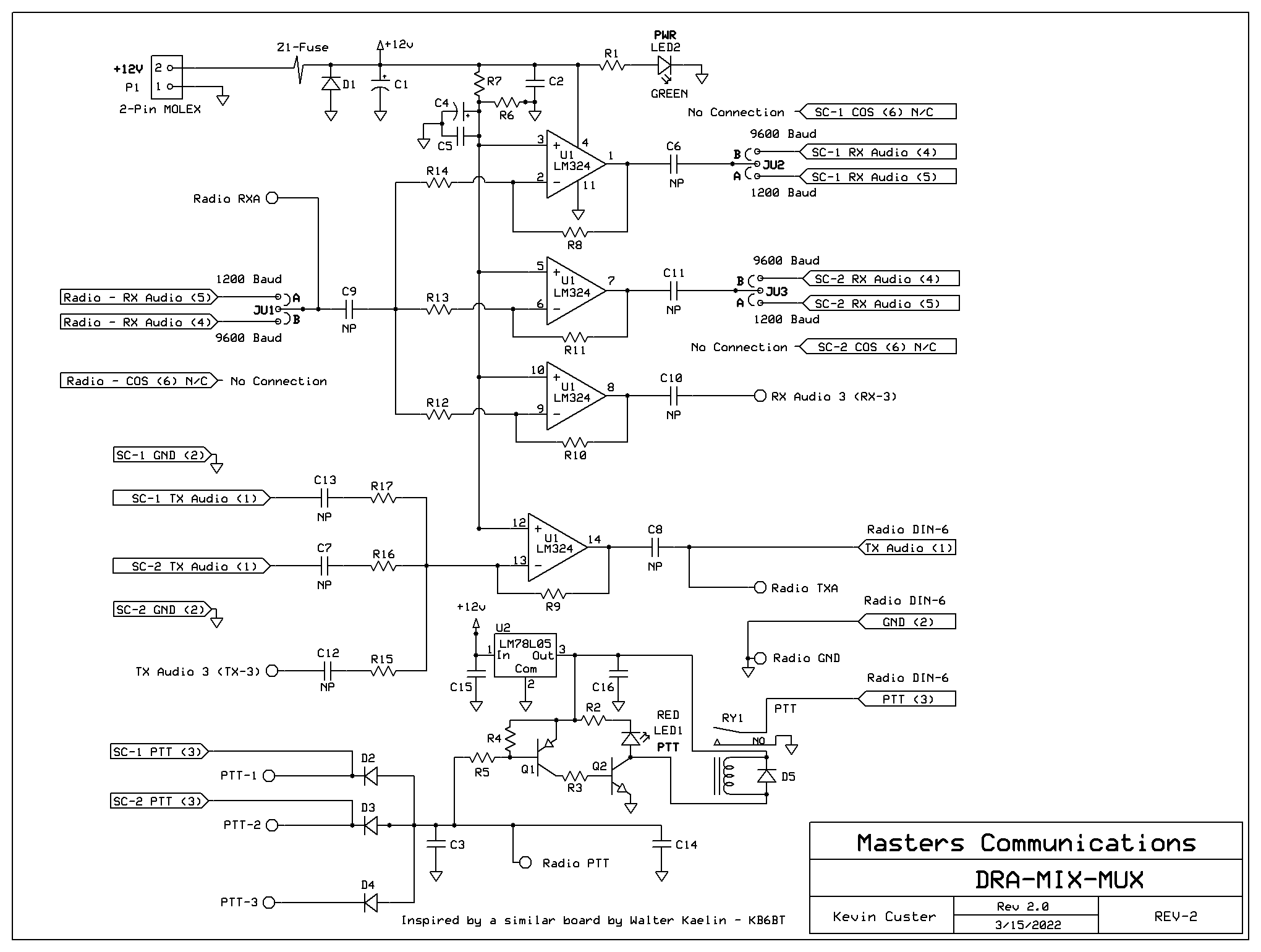
REV2 boards adds a relay for keying the radio PTT. Some ICOM radios require this.
Top side of DRA-MIX-MUX circuit board - shown slightly enlarged.
(Click photo to show a larger image)
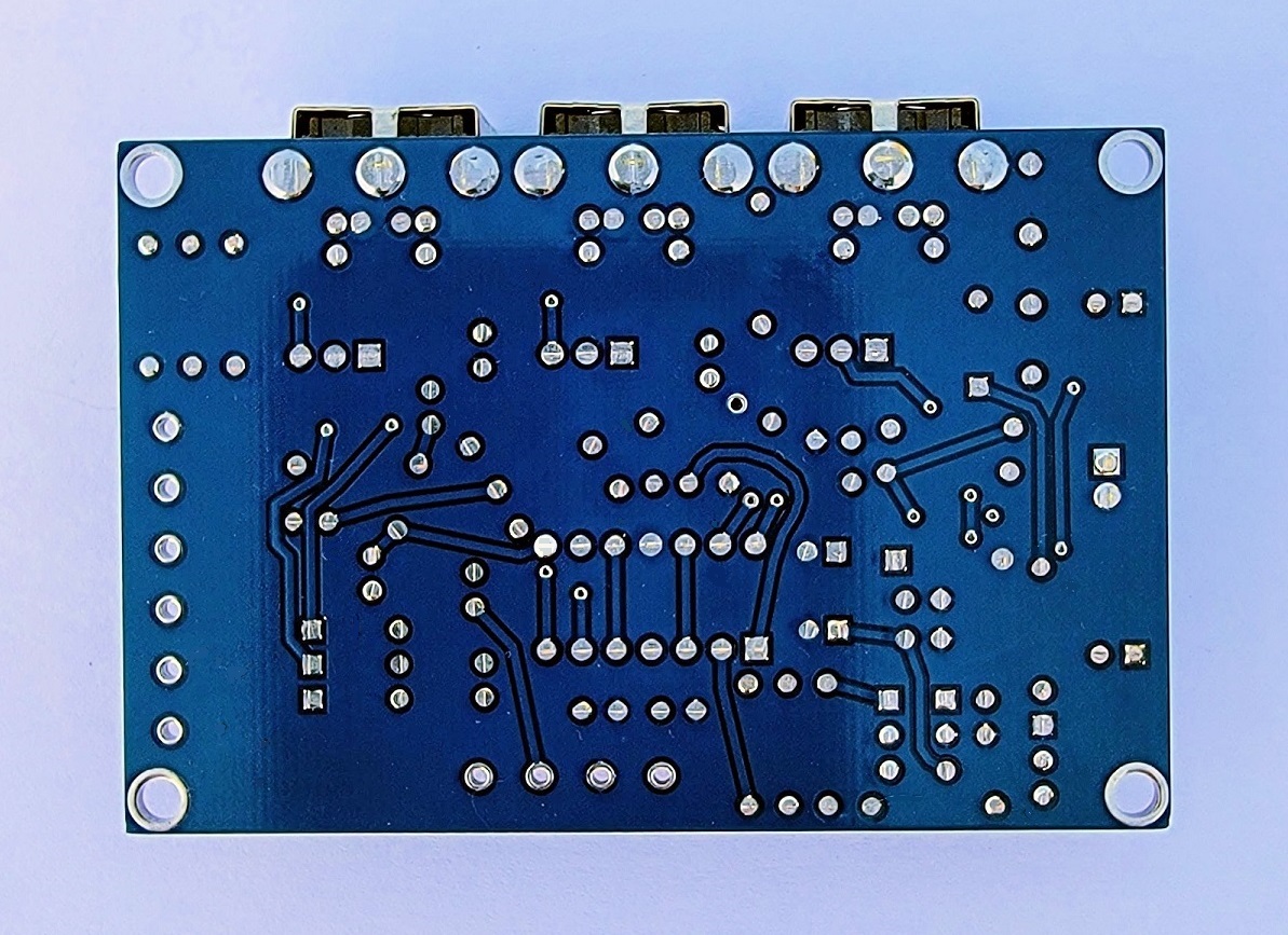
Bottom side of DRA-MIX-MUX circuit board - shown slightly enlarged.
(Click photo to show a larger image)
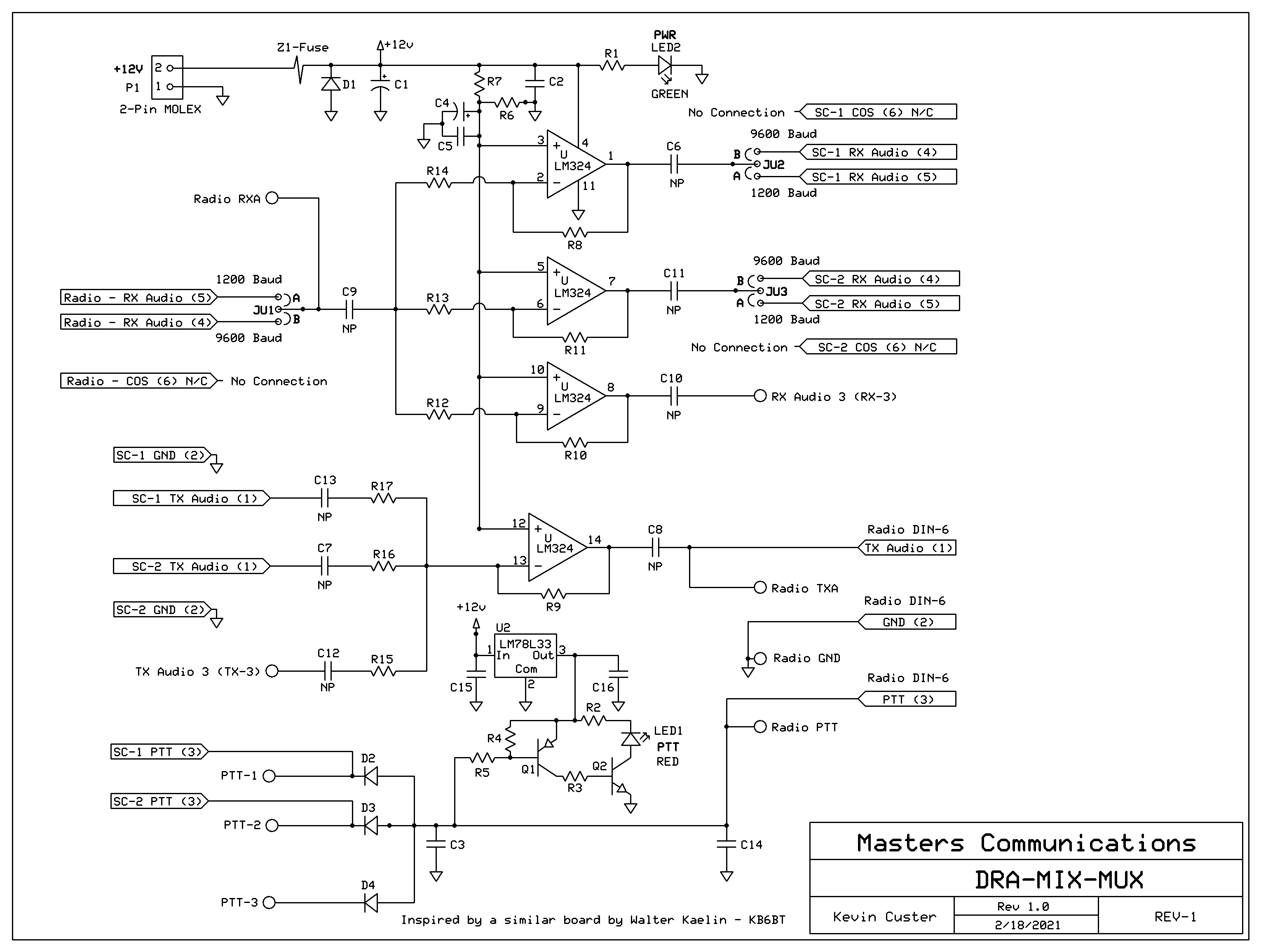
Schematic Image - REV1 - Click to download a high quality PDF.
Schematic Image - REV2 - Click to download a high quality PDF.
Its operation is pretty simple:
1 - The Green LED illuminates when power is applied.
2 - Any radio interface or sound card can assert the PTT to the radio. This operation is logically
"OR". Any of the three PTT inputs when grounded will cause the radio to transmit and the Red PTT
LED to illuminate.
3 - All sound card and/or modem transmit audio sources are resistivity mixed together, and buffered
to create one composite TX audio supplied to the radio.
4 - The radios receiver audio is resistivity split and buffered to supply RX audio to all sound cards or
modems.
Parts List:
If you purchased our kit, refer to the parts list and make sure you have all of the components
you need to build it.
Click here
for Parts List.
Construction/Assembly:
Click here for assembly instructions and construction notes - with large photo.
Jumper Settings:
Click here
for Header / Jumper settings and other board connection assignments.
Installation:
This device is intended to be installed inside a plastic box for protection.
Refer to the schematic for the pinout of the Mini-DIN-6 where all of the logic signals and
audio signals are listed.
Recommended powering requirements:
The board needs to be supplied with 12 VDC.
Secure PayPal ordering is available on the DRA-MIX-MUX main page.
Email Kevin
Custer for support, ordering information, order by check, or support of this
exciting product.
Product of Masters Communications, all rights reserved.
Specifications may change without notice.
Images property of Kevin Custer - W3KKC
Board layout by Kevin Custer - W3KKC.
HTML December 7, 2021, W3KKC All Rights Reserved!