Custom Products from Masters Communications

|
Custom Products from Masters Communications |
|
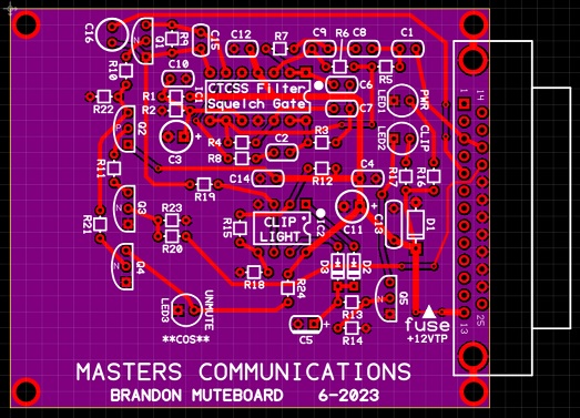
Brandon Muteboard - REV2
Actual Size Brandon Muteboard PC board.
(Click image to enlarge)
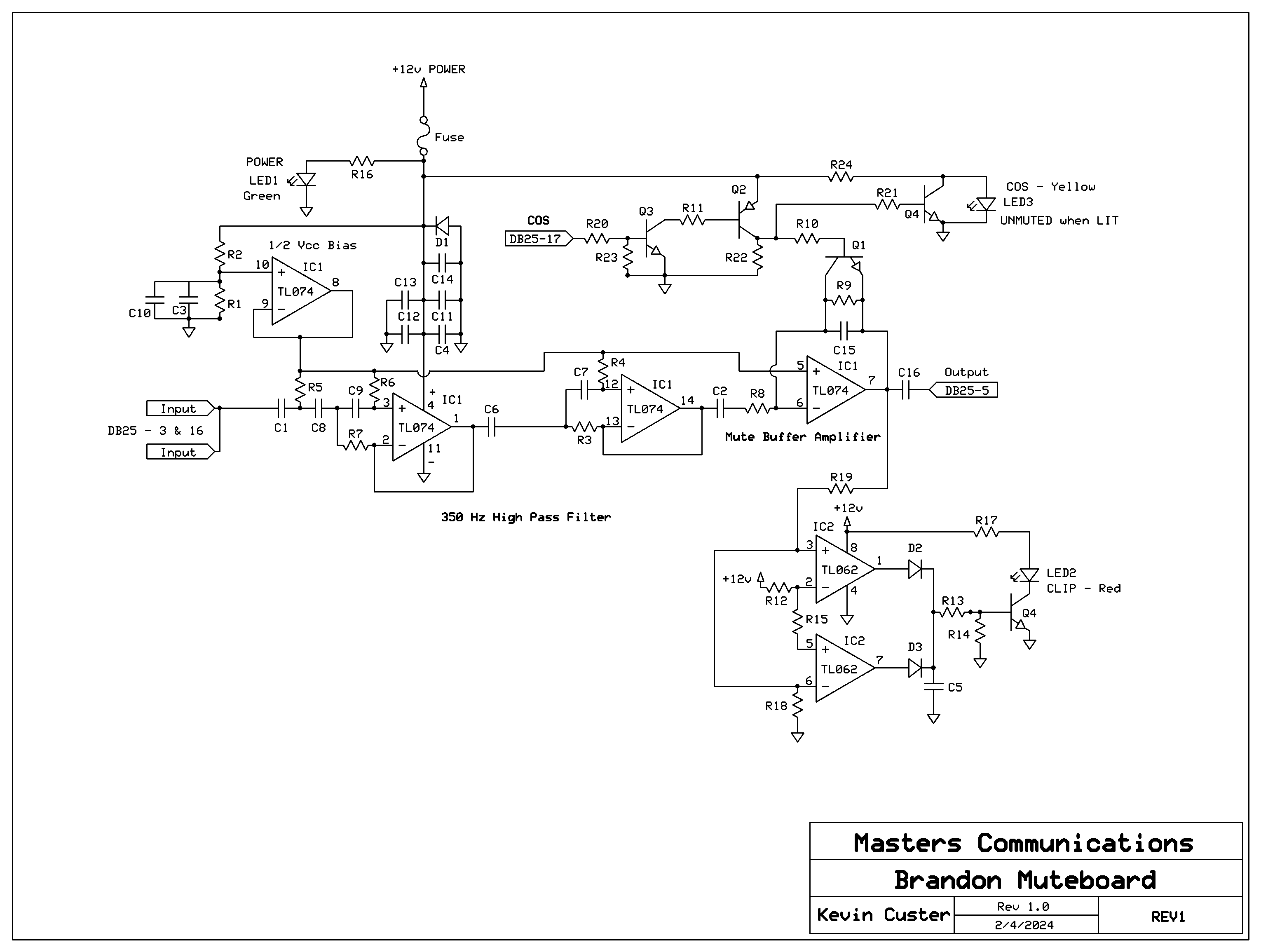
Schematic Image - Click to download a PDF file.
Overview:
This board will provide quality receiver audio for driving a repeater controller or other radio
interface device.
It requires a few hundred mV RMS of discriminator audio, COS logic, and a source of DC power.
If you purchased our kit, refer to the parts list and make sure you have all of the components
you need to build the kit.
Click here
for Parts List.
Construction/Assembly:
Assembly Instructions Assembly
instructions and construction notes - with large photo.
Installation:
This device is intended to be installed inside a radio or project box for protection.
Refer to the schematic for the pinout of the DB25F where all of the logic signals,
power connections, and discriminator audio input is listed. Pin 16 on the DB25 can be
used to supply discriminator audio to your controller or other audio interface.
Click here
for DB25 and other board connection assignments.
Recommended powering requirements:
The board requires a recommended minimum of 10 VDC. The maximum recommended voltage is 16 VDC.
Current is 10mA standby and 50mA illuminating all of the LEDs.
Recommended discriminator audio input level:
For best results and leaving some headroom for dynamic range,
an input of at least a few hundred mV RMS of raw discriminator audio at the input of the board
is required. A level of 8V P-P is acceptable with at least 10VDC powering the board.
About the audio inputs and outputs.
There is one audio input that is sourced from the receivers discriminator or detector. There is one
audio output that has been PL filtered, de-emphasized and squelch gated.
About the COS logic input.
There is one logic level input (DB25 Pin-17) (COS) to control the muting / unmuting of the audio.
The COS logic line requires an active low with a pull-up or inverted active high. Suitable
logic would deliver 0 volts unsquelched and 3 or more volts squelched into a 10k load. This input
can be fed from a SC-50(DW) or SC-75(DW) pin 17 - or its active low COS. Any logic that completely
turns the Yellow LED off (and on) is acceptable. If using an "open collector" NPN transistor to
drive the logic input - install JU1 (added on REV2) to provide the bias necessary to switch the COS logic line
and mute the audio when the receiver is squelched. On REV1 boards, do this externally.
Status LEDs.
There are three status LEDs for visual indication of DC power, unmuting, and clipping. They are
Green, Yellow and Red - respectively.
Secure PayPal Ordering - available from the main page.
Email
Kevin Custer for support, ordering information, order by check of this exciting product.
Product of Masters Communications, all rights reserved.
Specifications may change without notice.
Images property of Kevin Custer - W3KKC
Board layout by Kevin Custer.
HTML September 15, 2023, W3KKC All Rights Reserved!