Custom Products for the Analog & Digital Radio Amateur Enthusiast

|
Custom Products for the Analog & Digital Radio Amateur Enthusiast |
|
Digital Measurement Unit (DMU)
For Analog & Digital Two-Way Radio
Applications
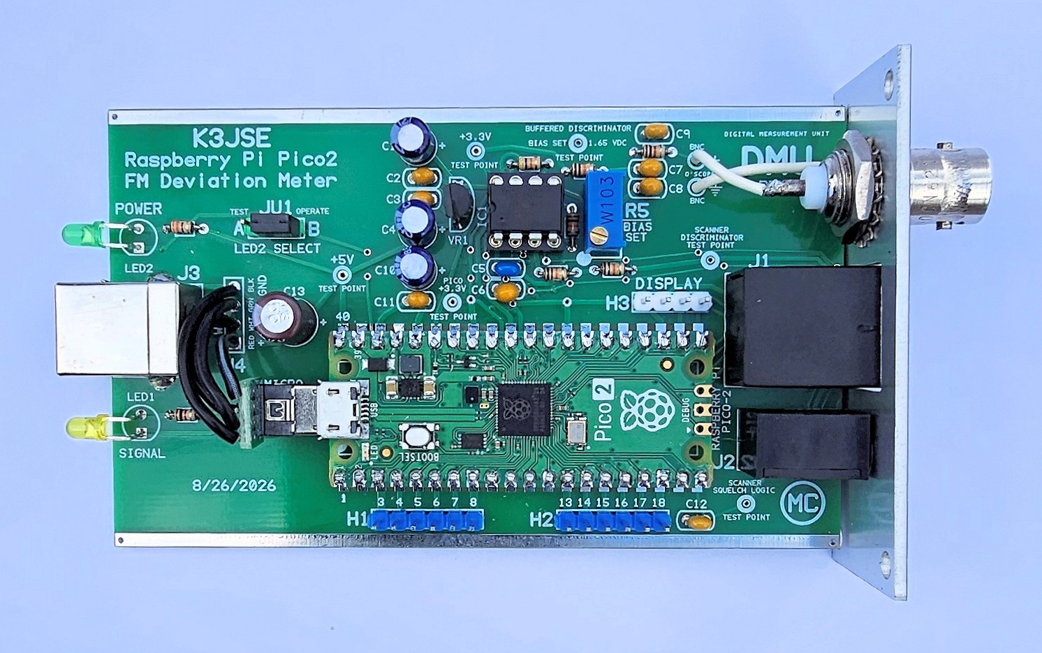
Top side of assembled K3JSE Digital Measurement Unit (DMU) Revison 2 circuit board - shown
slightly enlarged.
(Click photo to show a larger image)
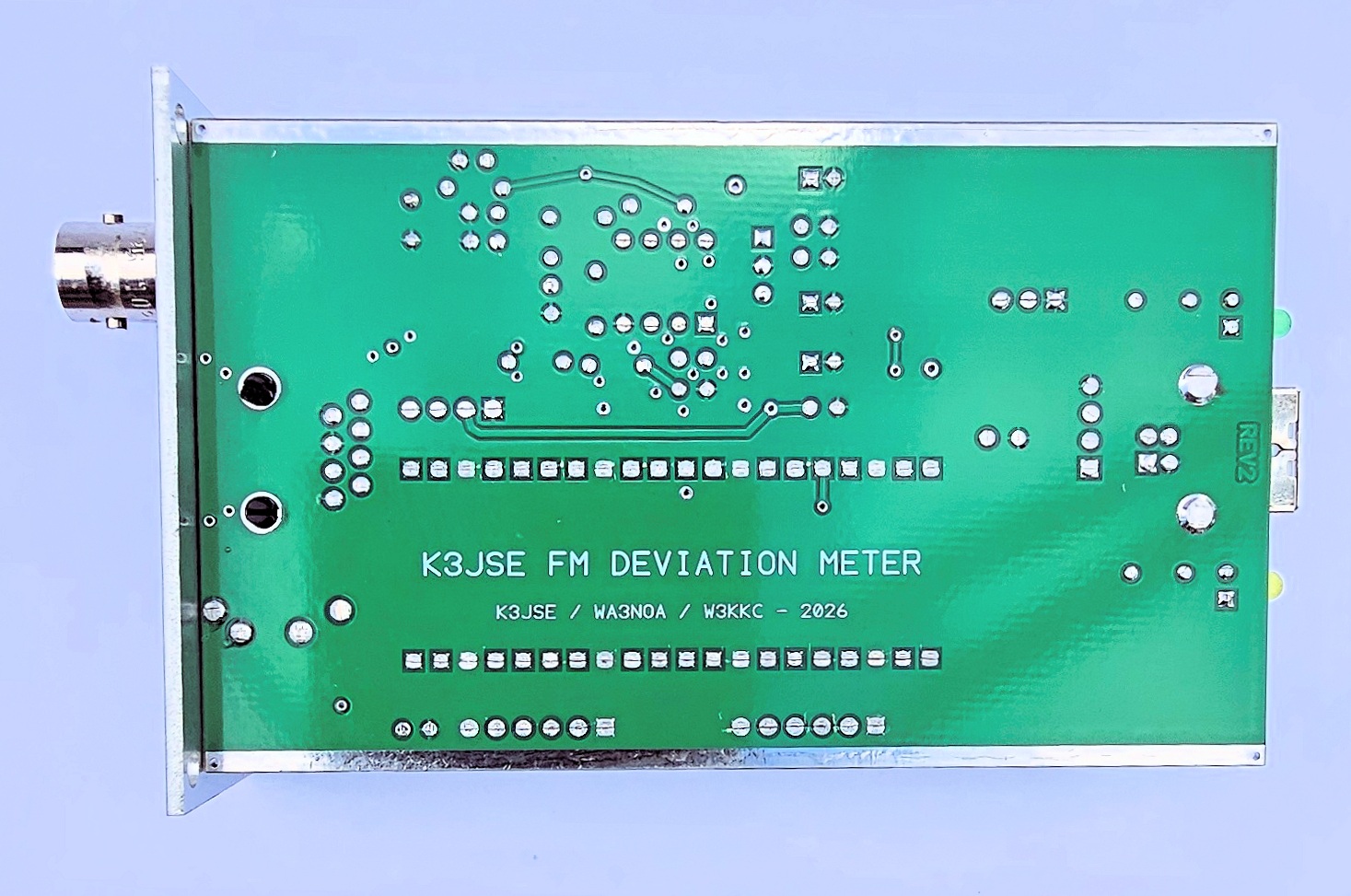
Bottom side of assembled K3JSE Digital Measurement Unit (DMU) Revison 2 circuit board - shown
slightly enlarged.
(Click photo to show a larger image)
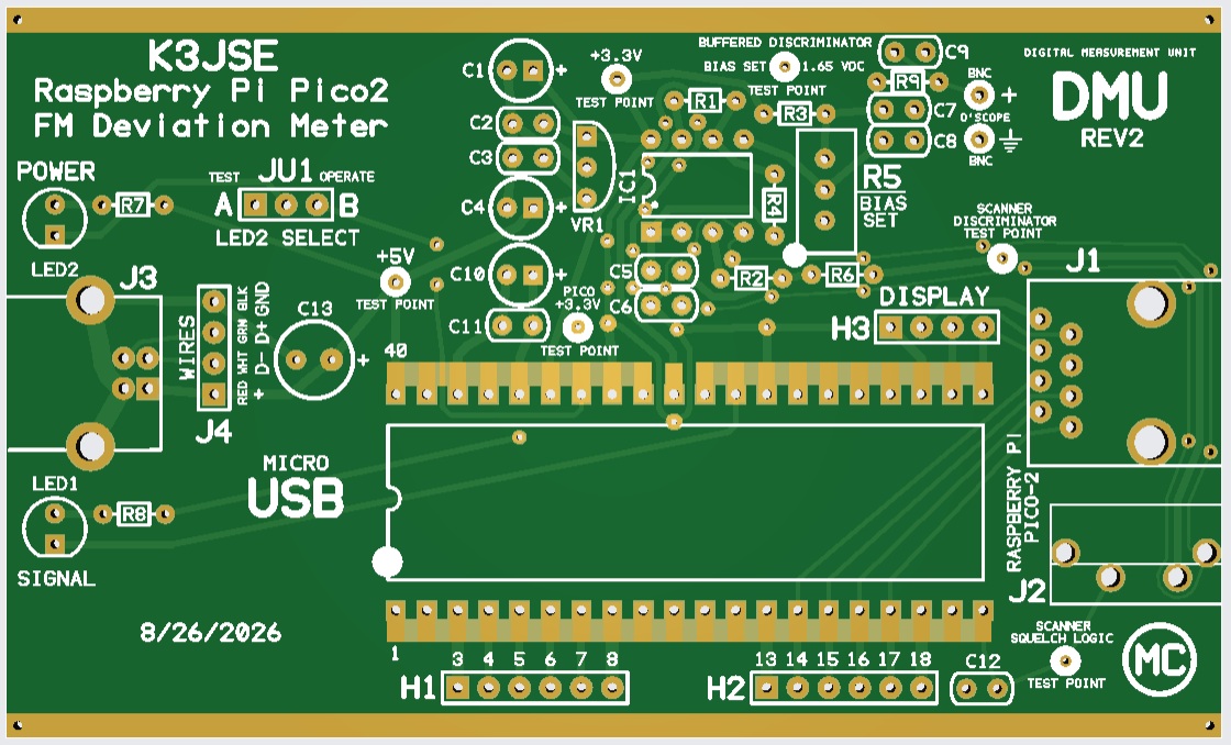
Computer render of the printed circuit board.
Please read through this entire article and the parts list at least
once before starting your assembly.
It will bring your attention to things that need to be done in order to prevent assembly errors
that might be difficult to recover from.
Click here
for the Parts List.
The parts list includes several construction notes too! Be sure to reference it along with this
article and the photos above to minimize the possibility of construction mistakes.
Assembly:
If you purchased our kit, refer to the parts list and make sure you have all of the components
you need to build the kit. All of the components are supplied with the kit, and while we make
every effort to be sure we didn't omit any components, it can happen. If you are missing anything,
or ruin something, just contact us.
Assembly can be done by personal choice, but you may find it easier to build in a vertical height order - installing the shortest components first, building toward the tallest. The LEDs already have their leads bent for proper installation. With the exception of the LEDs which are installed last and don't go against the board, all other components are installed tight against the circuit board.
Start by installing all resistors. Some resistors color bands may be hard to make out. If in doubt, use an ohm meter to verify the value before soldering it in place. Bend both of the resistor leads sharply at the body at a 90 degree angle.
Install the shortest capacitors. Small capacitors are identified as follows: 47 or 470 = 47pF, 102 = 1000pF, 471 = 470pF, "104" = 0.1uF. In other words the first two digits are the value and the third digit (if present) is the number of zeros you add to determine the final value. These small capacitors are not polarized and can be installed either way.
Install the IC socket - match the notch to the silkscreen.
Now, install the 3, 4 and 6 pin headers. NOTE: NO header is installed into location J4.
Next, install the voltage regulator (flat to flat on silkscreen). The silkscreen has "VR1" next to the part.
Plug the 8-pin integrated circuit into the machine socket observing the orientation notch, matching it with the socket.
Install the larger / taller electrolytic capacitors. Make sure you get them oriented correctly. The + of the polarized capacitors go into the holes with the square pad and + sign just outside of the outline.
Next - Install the multi-turn potentiometer R5. The board has a large white dot that matches up with the end of the control with the brass adjustment slot. Orient is as shown in the photo and solder tightly against the board.
Install only the USB-B socket connector - not the other two taller connectors.
Before proceeding - plug the provided USB cable into the USB-B socket and power the board using a computer or USB charger. Check the +5V and the two +3.3V test points using a multi-meter. If these check out - proceed with the steps below. If not - fix what's wrong. The silver metal body of the USB connector and tin plated 'rails' on each side of the board are ground.
Now - adjust the R5 potentiometer while reading the voltage at the Bias Setpoint Test Point to 1.65 VDC. If this doesn't adjust - stop and troubleshoot. This is NOT a calibration, it's merely testing the calibration circuitry for the ability to adjust.
Now install the Raspberry Pi Pico2 board onto the DMU board. This can be done either by using the castellated holes or regular 20-pin headers. Install the shorter part into the DMU board - the longer part will mate with the Raspberry Pi PICO2. All 40 locations should be soldered - but you can choose to only solder the pins that are absolutely necessary. They are 3-8, 13-18, 20, 21-23, 28, 29, 31, 33-36, 38 and 40.
Next, install the RJ45 and 3.5mm socket connectors.
Then, install the 2 LEDs. NOTE the flat on the LEDs lens and the circuit board outline to insure the correct orientation of the LEDs. The LEDs have their leads pre-bent so they will fit into their holes of the front panel and mount properly. Temporarily place your front panel over the USB connector to get the alignment right while soldering them in place. Reheat and readjust if necessary - before trimming the leads.
Now - Install the BNC connector. A wire is necessary to complete the ground comnnection. Wrap a piece of stripped #24 white wire aroud the entire circumference of the BNC connector. Insulation should exist between the body of the connector and the ground hole in the DMU board. Place the washer over the wire and then place the nut. Tighten up so the BNC connector is tight and doesn't rotate, while keeping the wire under the washer. Now cut the insulated tail slightly longer than necessary and strip the insulation and solder the ground tail into the ground hole on the DMU circuit board.
Then - using another piece of insulated wire, strip and solder into the center conductor cup. Then cut the wire slightly longer and solder the center conductor wire into the + hole on the DMU circuit board.
Before installing the board into its metal case, go to
the Calibration Article.
After calibrating the unit, place the front panel with its four screws onto one end of the case. Slowly slide the board into the lower set of rails from the rear making sure the LEDs are aligned and come through the front panel when it's fully inserted. Now - position the rear panel and secure with the remaining four - 2.5mm black Phillips head screws.
Support Documentation
Click here for DMU support documentation.
Installation:
This device is intended to be installed beside the scanner and connected with a short male
to male stereo cable and RJ45 (Ethernet) cable to the optional display.
Calibration:
A complete calibration procedure is available from
the Calibration Article.
Secure PayPal ordering is available on the K3JSE DMU main page.
Email Kevin Custer for support, ordering information, order by check, or support
of this exciting product.
Product of Masters Communications, all rights reserved.
Specifications may change without notice.
Images property of Kevin Custer - W3KKC
Board layout by Kevin Custer - W3KKC.
HTML August 2, 2026, W3KKC All Rights Reserved!