Custom Products from Masters Communications

|
Custom Products from Masters Communications |
|
Model SC-50 & SC-50DW
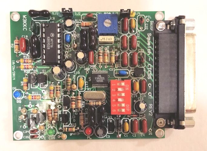
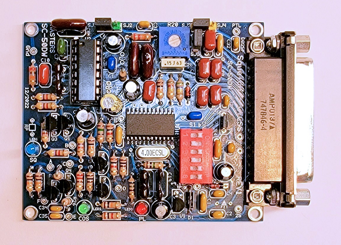
Actual Size SC-50 and SC-50DW PC boards.
(Click image to enlarge)
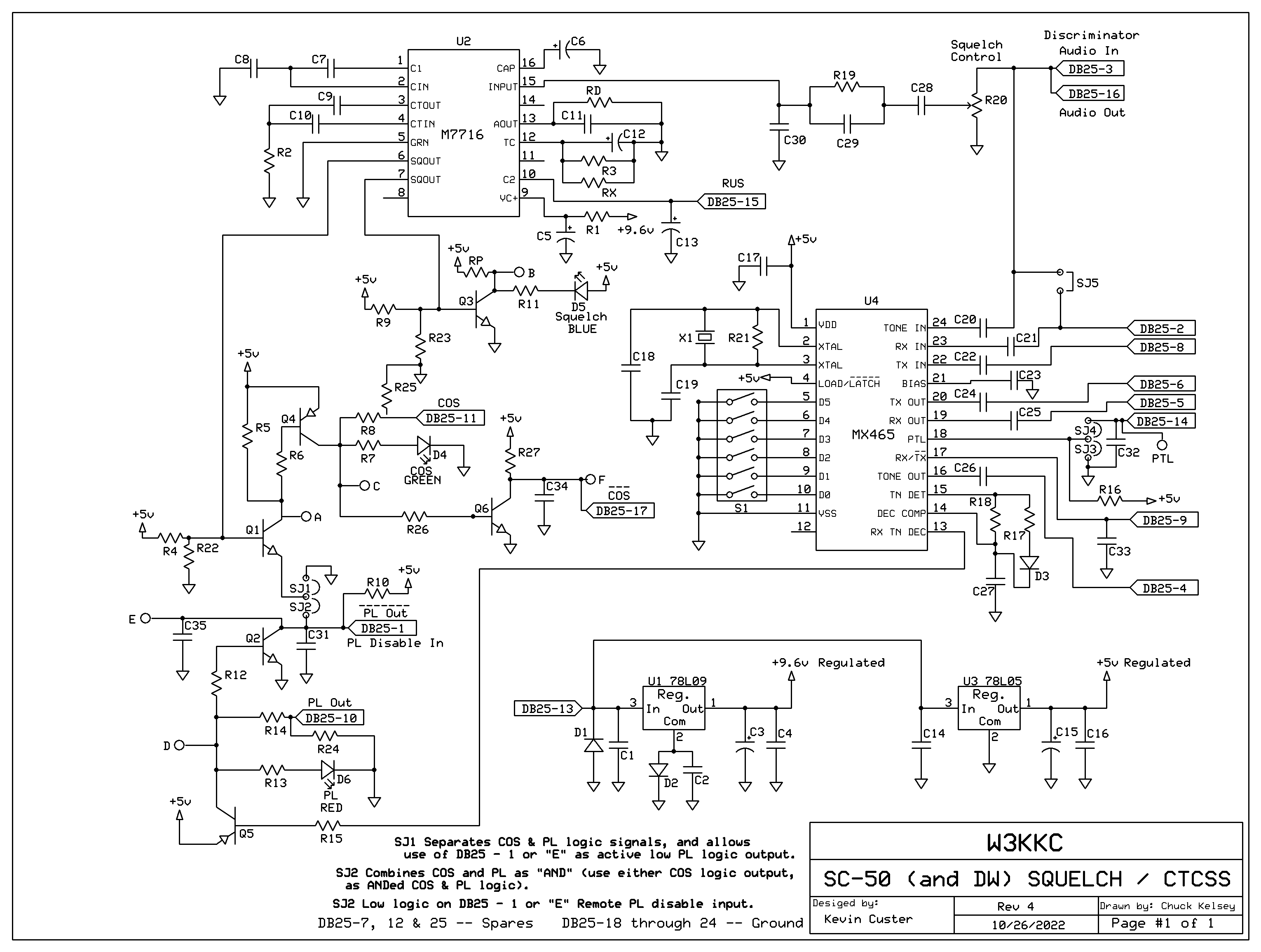
Schematic Image.
(Click image to download a PDF copy)
Overview:
This board will provide quality logic signals for driving a repeater controller or other radio
interface device like URI, RIM, or FOB. It requires a few hundred mV RMS - AC coupled
discriminator audio and a source of power.
The logic signals can be used together to create a single logically AND'ed output.
This is nice for supplying logic to a controller or other device which only has one logic input,
and you want the ability to use both COS and CTCSS in a "AND Squelch" configuration.
It uses the Motorola MICOR SC6709 squelch IC (also marked M6709
or M7716 depending on manufacturing date).
If you purchased our kit, refer to the parts list and make sure you have all of the components you need to build the kit.
SC-50 Parts Lists:
Construction/Assembly:
If you need assistance with the assembly, Click here for assembly
instructions and construction notes - with large photos.
Installation:
This device is intended to be installed inside a radio or project box for protection.
Refer to the schematic for the pinout of the DB25F where all of the logic signals,
power connections, and discriminator audio input is listed. Pin 16 on the DB25 can be
used to supply discriminator audio to your controller or other audio interface.
Click here
for DB25 and other board connection assignments.
Setting the squelch and CTCSS tone frequency:
Click here
for DIP switch settings.
1 = ON
0 = OFF
In the photos at the top of the page, the SC-50's are set to 123.0 Hz.
Recommended powering requirements:
The board requires a recommended minimum of 12 VDC to put the regulators into full
regulation. While the board will operate at a lower voltage input,
the noise squelch circuitry may become erratic. The maximum recommended
voltage is 16 VDC, however, the voltage regulators will survive up to 24
VDC before damage occurs. The board has been tested with as low as 10 VDC and
the board still seemed to operate normally.
Recommended discriminator audio input level:
We have found that a squelch pot setting of 1/4, open (9 o'clock) [for the place
where on/off squelch action occurs] results in very good noise and CTCSS detection.
That's about 750mV RMS (2.1V peak to peak) of noise at the board input.
(No RF input signal to the receiver). While the M6709 is happy with as little as 15mV
RMS of signal, (at its input pin 15) this starves the CTCSS detection circuitry, and it
won't decode down into the noise as well. For best CTCSS detection and dynamic range,
an input of at least a few hundred mV RMS of raw discriminator audio at the input of the board
is required. This equates to about .85V peak to peak
at a minimum. 750mV RMS (about 2.1V peak to peak), is about the maximum amount of audio
that should reach the input of the board. If you have too much audio,
a simple resistor in series with the input will create a voltage divider (against the squelch pot)
and reduce the input to a more desirable level. A value in the 47k to 330k range is
approximately what should be expected, depending on the audio level that is too high.
Input levels are somewhat dependent on the type of receiver, characteristics of
the discriminator, and how much high-frequency energy is present in the recovered audio.
If you have too little audio, a simple audio amplifier may be required to meet
the required input level of the board. Refer to
this amplifier project (the first one) if necessary.
Explanation of the logic signals and other pins:
Active high and active low outputs for CTCSS and COS logic are available. Both active high
and active low are available for the COS logic output, irregardless if this output is being
used in "AND" mode. The outputs are open collector and are available on the DB25,
and from 6 holes on the circuit board. These outputs can be used for operations that
are beyond the original scope of this board.
For "AND" mode, the COS output is the one that's used. Pull-down resistors are included on the logic high outputs. Obviously if you are using this board and need active low outputs you should be using the outputs connected to the NPN transistors, but, the on-board pull-down resistors can make circuitry respond correctly when using the active high PNP outputs.
All logic is sourced from +5V and ground. +5 volts is the logic value expected directly from the collector of a PNP logic transistor that is biased on. Ground is the logic value expected directly from the collector of a NPN transistor that is biased on.
The normal outputs that connect to the DB25 should satisfy most of the devices you'll connect to this board. For those instances where they don't, you can use the outputs labeled A - F. These outputs are available from "holes" on the circuit board, marked A - F on the silkscreen. These outputs connect directly to the collectors of the logic transistors before any current limiting resistors. There are three extra pins on the DB25 pins 7, 12, and 25 which can be jumped to any of these additional outputs. Caution should be given to the use of any of these additional outputs as they are unprotected, and misuse will cause switching transistor failure. While the PNP transistors have the over-current protection of the 5 volt regulator, there is no protection for the NPN to ground. Be certain that your connection to these outputs don't exceed the capabilities of the board or switching transistor.
The SJ1/SJ2 header allows pin 1 on the DB25 to be an input or output. If the user desires the COS and CTCSS outputs to operate independently, they would place a jumper in the SJ1 position. This allows pin 1 on the DB25 to be an active low CTCSS logic output.
If this header is jumped with SJ2, the logic signals are used together in AND Squelch mode. If SJ2 is in place, grounding pin 1 of the DB25 disables the requirement for CTCSS. In other words it disables the CTCSS requirement and the logic at the COS outputs are only controlled by the status of the noise squelch - CTCSS is ignored or "disabled".
The SJ3/SJ4 header allows the PTL function to be selected remotely. Normally, this jumper will be in the SJ3 position - which disables the remote select option. If you want to use this option, place the jumper in the SJ4 position and selectively ground either the "PTL" hole or pin 14 on the DB25. Refer to the manual download below to see what this function is, and what it does.
SJ5 takes discriminator audio and puts it into the RX audio filter input so you don't have to wire two pins together or otherwise route discriminator audio into the unit twice. This is beneficial in the installation of the SC-50 in a Yaesu System Fusion repeater, or any other installation where you desire to have CTCSS reject filtered receive audio. SJ5 is simply a shorting bar that parallels pins 2 and 3 on the DB25.
There is an option to disable the fast/short squelch operation of the M6709/7716. This is accomplished by adding a 22k resistor in the "RD" position. Why would you want to do this? Such as when you're using a delay line in a conventional controller or rxsquelchdelay in app_rpt. Of course you're losing one of the best features of the M6709/7716, but if you're using fixed audio delay, it makes sense to not have two different closure times.
There is an option to shorten the long squelch hang time. This is done by adding a resistor in the "RX" position. This value can be whatever the user chooses as it will work in conjunction with the original 180k. On UHF repeaters where the flutter is generally very rapid, the original 200 mS long squelch time can be unnecessarily too long.
Third Party Compatible Projects:
MABEL is an interface and software that allows analog control of the Yaesu DR-1X repeater and access
to the AllStar VOIP network with the Raspberry Pi3 and AllStar Asterisk. (Offsite Link)
Information on the FX465.
Click here
to download a manual for the FX465-D5
Secure PayPal ordering is available from the main page.
Email
Kevin Custer for support, ordering information, order by check, and/or quantity pricing of this exciting product.
Product of Kevin Custer - W3KKC, all rights reserved.
Specifications may change without notice.
Images property of Kevin Custer - W3KKC
Board layout by Chuck Kelsey.
HTML November 20, 2014, W3KKC All Rights Reserved!