Custom Products from Masters Communications
Phone: (814) 313-4036

|
Custom Products from Masters Communications Phone: (814) 313-4036 |
|
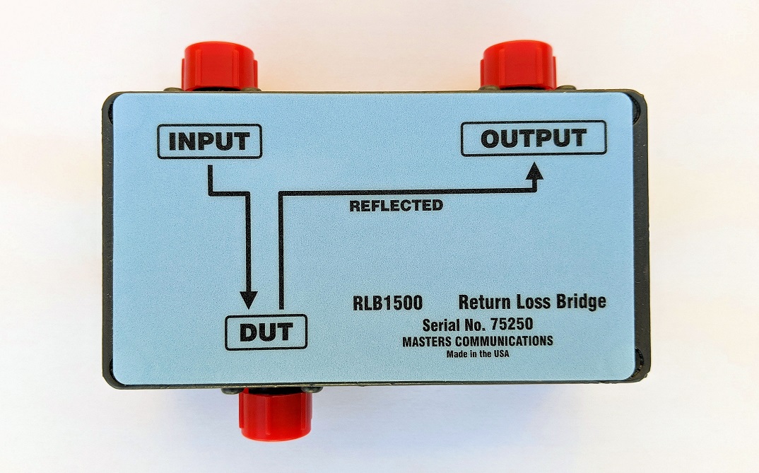
RLB1500
Commercial quality 0.5 - 1500 MHz
50 ohm Return Loss Bridge - $750.00
Specifications (includes performance chart)
What is it, and what does it do?
A return loss bridge can turn your service monitor or signal generator / signal receiver
into an accurate antenna VSWR analyzer. It will provide the same accuracy as antenna
analyzers costing thousands more. The RLB1500 is a commercial duty 50 ohm, 0.5 - 1500 MHz return
loss bridge (RLB) for antenna/feed line, cavity, and duplexer testing and alignment.
Our bridges are individually built and tested and include an actual proof of performance graph.
This unit has a 0.5 - 1500 MHz range and minimum 35 dB directivity (40 dB typical).
The unit has high quality type N connectors for all ports and is configured with the input
and output ports conveniently on the same side. The design will withstand 4 Watts
of accidental power input to the DUT port. Use your existing rf generator and receiver/power
meter/spectrum analyzer to make accurate measurements. The unit is designed for use in 50
ohm systems.
The basics of a Return Loss Bridge:
In simple terms, the return loss bridge is a device used to measure RF power reflected
from a load or device under test (DUT) when power is sourced to the device through the
RLB. The return loss bridge has 3 ports. An RF signal generator is applied to the input
port. The output port provides an RF signal to go to a measuring device such as a spectrum
analyzer, power meter or other device used to measure this signal. The DUT port connects
to the device that you are testing (antenna, coax, etc.). A signal is generated into the
input port. The RLB applies this signal to the DUT. The DUT will reflect a portion of the
signal that it receives (due to impedance mismatch). This RF signal appears at the output
port. The closer your DUT impedance is to 50 ohms, the lesser the signal will be at the
output port. A perfect 50-ohm DUT will have no reflected power so a perfect RLB will have
no output signal at its output port (infinite return loss). If a non-50-ohm load is at
the DUT port, there will be an RF signal at the output port. The extreme cases are for
the DUT to be a short or an open connection. This will cause maximum reflected power and,
therefore, maximum signal at the RLB output port. Return loss is measured from the worse
case (short or open) with 100% power reflected. It's the difference amount in dB of the
reflected signal of your DUT compared to the worst case reflected signal. The further you
go from "worse case" the better. The higher the return loss number, the closer the DUT is
to 50 ohms. This is somewhat the opposite when compared to SWR (high SWR means high
reflected power or poor match) For example: with an open or short connected to the DUT
port and an RF signal source generating into the RLB input port, let's say we measure the
RF power at the RLB output port to be -22 dBm. If the open or short were replaced with
your load at the DUT port, the amount of power at the RLB's output port would then change.
If the output signal is now measured to be -42 dBm, this would be a return loss of 20 dB.
The amount of reflected power is 20 dB less than the worst case. This is equal to an SWR
of 1.22:1. If this were an antenna, it would be considered an excellent match with about
1% of the power to the antenna reflected. A return loss of 10 dB would correspond to an
SWR of 1.91:1 with 10% of your power reflected. This is generally considered a poor match.
Most commercial systems want to see a return loss of 18 dB or better.
Directivity:
Directivity is the measure of how well the RLB isolates two opposite traveling (forward
and reflected) signals. As the reflected signal becomes smaller and approaches the
specified value of the RLB directivity, the measurement uncertainty becomes larger. To
get accurate return loss (SWR) measurements, it's important to have a bridge with
directivity of 10 to 20 dB higher than what you want to measure. The higher the
directivity, the greater the accuracy the RLB can measure small signal levels of
reflected power. A perfect 50-ohm load should have infinite return loss, which translates
to no output signal from an RLB. If we could build a perfect RLB, the output port would
show no signal with a perfect 50-ohm load. In the real world, the highest quality RLB
would show a return loss of up to 50 dB. 50 dB would be pushing the physical limits
because the N connector itself has a tiny amount of return loss. A higher quality bridge
will have higher directivity than needed to provide better accuracy at all levels.
The RLB1500 has guaranteed directivity of 35 dB with typical directivity being 40 dB or
better over the 0.5 - 1500 MHz range. A 20 dB directivity means that you'll see as little
as 1% of reflected power. A directivity of 30 dB is 0.1% and 40 dB is 0.01% ( 1/10000 of
worst case reflected power level). The RLB1500 return loss bridge is individually tested and
includes a performance evaluation graph.
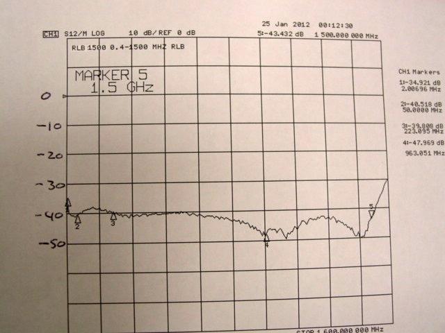
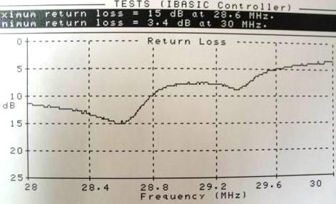
Here is a typical return loss graph printed from an HP E6380A Service Monitor. The left graph shows the typical response when sweeping the Narda 50 ohm precision load. Sweeping to 1500 MHz shows this return loss bridge is working properly with a better than 35 dB directivity over this range. The graph on the right is a sweep of a 10-meter yagi antenna. At the top, the maximum return loss was 15 dB at 28.6 MHz. Generally, you want to sweep just 1-2 MHz to get the resolution needed to see the best impedance match, as well as the usable frequency range. The RLB1500 is a valuable tool for duplexer tuning, as the frequency which exhibits the lowest insertion loss and the frequency which exhibits the best impedance match may not coincide.
See this off-site link: Duplexer Tuning with a similar return loss bridge for details.
The RLB1500 was compared to several higher priced units and provided similar results
for return losses below 40 dB.
| VSWR | Return Loss |
Power Refl% |
Power Trans% |
|---|---|---|---|
| 1.01 | 46.1 | 0.0 | 100.0 |
| 1.02 | 40.1 | 0.0 | 100.0 |
| 1.06 | 30.7 | 0.1 | 99.9 |
| 1.10 | 26.7 | 0.2 | 99.8 |
| 1.20 | 20.8 | 0.8 | 99.2 |
| 1.22 | 20.0 | 1.0 | 99.0 |
| 1.30 | 17.7 | 1.7 | 98.3 |
| 1.50 | 14.0 | 4.0 | 96.0 |
| 1.91 | 10.0 | 10.0 | 90.0 |
| 2.00 | 9.5 | 11.1 | 88.9 |
| 3.00 | 6.0 | 25.0 | 75.0 |
| 4.00 | 4.4 | 36.0 | 64.0 |
| 5.00 | 3.5 | 44.4 | 55.6 |
| RLB1500 0.5 - 1500 MHz RLB Specifications (includes performance chart) | $750.00 |
| Narda N male 50 ohm 35 dB precision test load with chart (these are hand-selected, used / tested) | $40.00 |
| MCL N male 50 ohm 40 dB+ precision test load with chart (these are hand-selected, used / tested - not always available) | $75.00 |
| MCL Load Upgrade to any kit on this page - substituted for the Narda | + $35.00 |
| QTY=2 - 24 inch N male to BNC male RG400 (made from new cable w/ H&S connectors) test cable set (2 cables - for input and output connections) | $40.00 |
| QTY=2 - 24 inch N male to N male RG400 (made from new cable w/ H&S connectors) test cable set (2 cables - for input and output connections) | $40.00 |
| 6 dB BNC to BNC fixed attenuators (QTY=2) for cable end to your equipment | $35.00 |
| 6 dB N male to N female fixed attenuators (QTY=2) for cable end to your equipment | $49.00 |
| Huber Suhner 4901.17.A 50 ohm power divider (used for distance to fault measurements - New) | $250.00 |
| RLB1500 Kit with Narda load, carry case, and test cable set (choice of N or BNC) | $890.00 |
| RLB1500 Kit with Narda load, carry case, (2) 6 dB BNC to BNC attenuators, and BNC cable set | $910.00 |
| RLB1500 Kit with Narda load, carry case, (2) 6 dB N to N attenuators, and N cable set | $920.00 |
| The carry case is a small customized "Pelican" type large enough to hold the bridge, cal load and test cables | |
| MCL Load Upgrade to any kit on this page - substituted for the Narda | + $35.00 |
| For HP8920 and 8921 owners:
RLB1500 Kit with Narda load, carry case, (1) 6 dB BNC to BNC attenuator, (1) 6 dB N to N attenuator, (1) N to N cable and (1) N to BNC cable |
$916.00 |
| The carry case is a small customized "Pelican" type large enough to hold the bridge, cal load, and test cables | |
| MCL Load Upgrade to any kit on this page - substituted for the Narda | + $35.00 |
| RLB1500 Super Kit: Includes carry case, Narda or MCL load, test cable set (your choice N or BNC), (2) attenuators (your choice N or BNC), and the Huber Suhner Power Divider |
$1100.00 |
| USPS Priority Shipping - Insured | Priced accordingly. |


Payment Methods:
We accept most Credit & Debit Cards and PayPal.
You do NOT need a PayPal account (or need to open one) to process the payment.
Sorry - I can not take orders over the phone.
We will send an invoice to you that you can pay securely online.
We can accept your company check. It must clear before your order is processed for
shipment. This can add days or weeks to an order.
This web page, this web site, the information presented in and on its pages is © Copyrighted 1995 and (date of last update) by Kevin Custer and multiple originating authors. All Rights Reserved, including that of paper and web publication elsewhere.
Updated as of date below - Kevin Custer