Custom Products from Masters Communications

|
Custom Products from Masters Communications |
|
Support Documentation
for
Model RA-DR1X
Looking for radio adapters for digital applications? See our new DRA-Series.
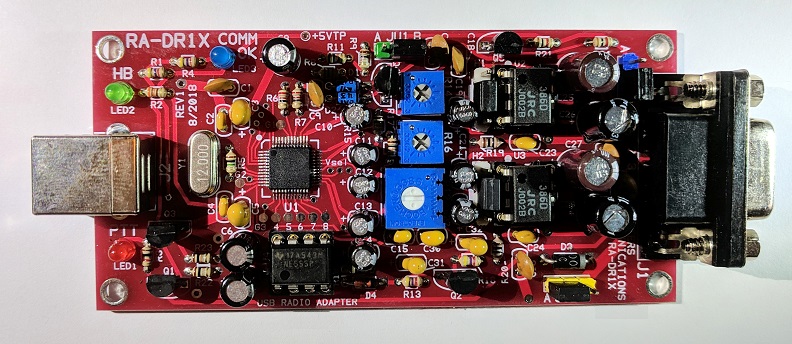
Top side of RA-DR1X board - shown slightly enlarged.
(Click photo to show a larger image)
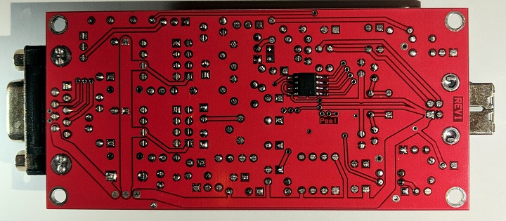
Bottom side of RA-DR1X board - shown slightly enlarged.
(Click photo to show a larger image)
Schematic Image - Click to download a high quality PDF.
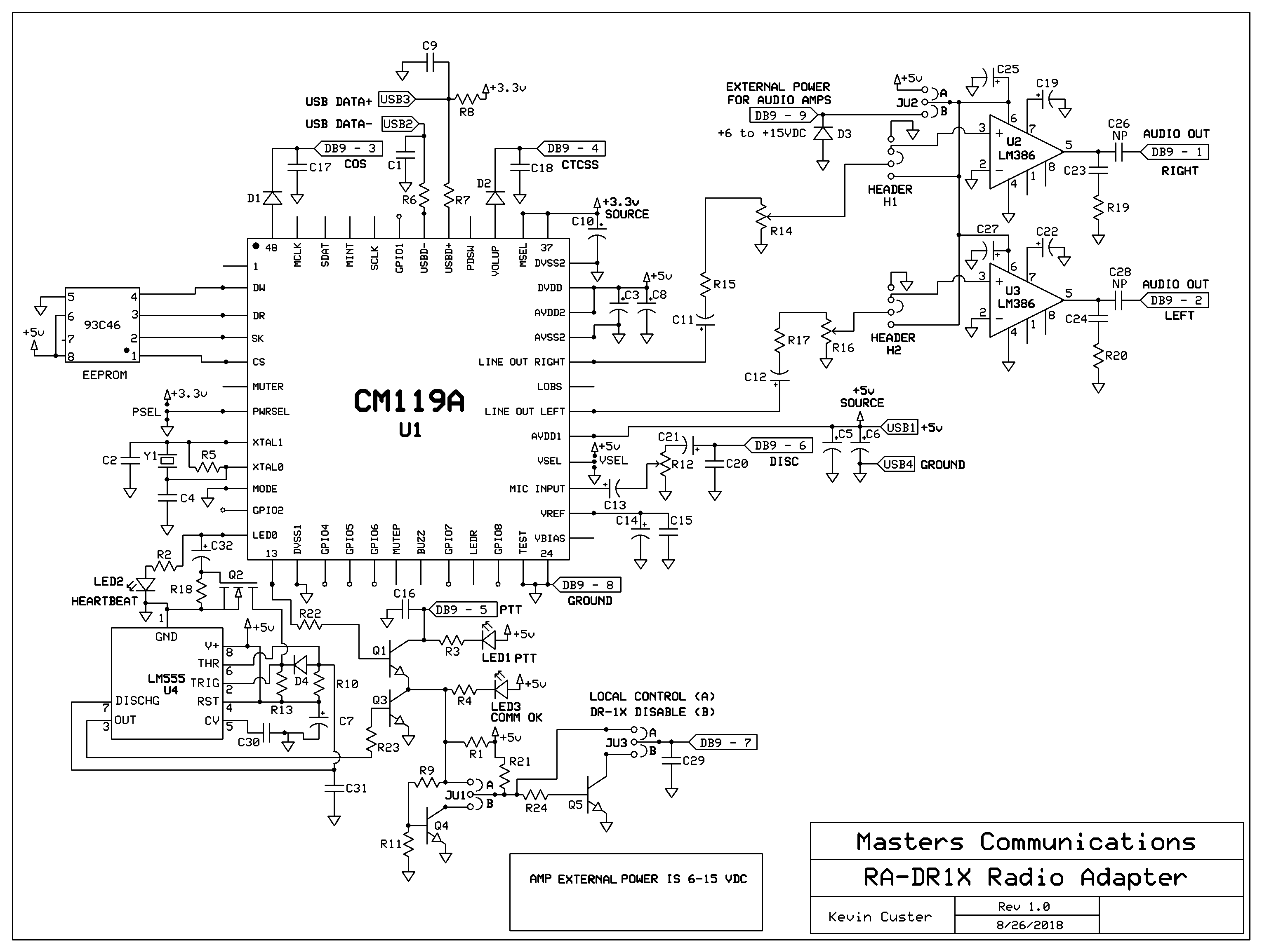
Circuitry wise, the RA-DR1X identical to the RA-40 with one exception,
it includes circuitry to allow the original in-cabinet controls to operate if something AllStar wise should fail.
Kits come with the surface-mount ICs preinstalled.
Parts List:
If you purchased our kit, refer to the parts list and make sure you have all of the components
you need to build it.
Click here
for Parts List.
Construction/Assembly:
Click here for assembly instructions and construction notes - with large photos.
Optional Metal or Plastic Case:
A Metal SC Case or
Plastic Case is available optionally for the RA-DR1X.
Choose either option from our PayPal ordering drop-down. Follow link for more information.
Installation:
This device is intended to be installed inside a radio, computer, or project box for protection.
Refer to the schematic for the pinout of the DB9F where all of the logic signals, power
connections, and audio signals are listed.
Click here
for DB9, jumpers and other board connection assignments.
H1 and H2 header pin assignments:
Click here for a detailed header pin explanation. The
primary purpose of the headers H1 and H2 are for installation of
optional FL-10 audio filters. The FL-10 is designed to be installed onto the header pins
directly or remotely by extending the four pins with wires. Jumpers are needed over the center
two pins if the optional filters are not installed.
Recommended powering requirements:
The board is supplied with 5 VDC from the USB connection. The audio amplifiers and optional
filters can run from this, or from an external power source of 6 to 15 VDC. Jumper JU2 controls
where the voltage is sourced from.
Recommended receive audio input level:
The RA-DR1X accepts the widest range of audio compared to any other similar radio adapter. The
input signal is attenuated by a potentiometer, giving the broadest range of acceptable levels.
As little as 20 mV P-P can be used with a setting of rxboost=1, and as much as 20 volts P-P
with a setting of rxboost=0.
Which C-Media chipset is used?
All RA-DR1X's are supplied with a Genuine C-Media CM119A, but the RA-DR1X board was designed
to be versatile. It will accept a CM119 (without the A) and even the CM108.
There are slight differences between these components, and the board can be 'programmed'
to accept any of the three.
Information on the CM119A.
Click here
to download a manual for the C-Media CM119A.
Information on the CM119.
Click here
to download a manual for the C-Media CM119.
Secure PayPal ordering available from the RA-DR1X main page.
Custom cables available from URI Cables. They can build a custom cable for the RA-DR1X for many radios.
Third Party Compatible Projects:
MABEL is an interface and software that allows analog control of the
Yaesu DR-1X repeater and access to the AllStar VOIP network with the Raspberry Pi3 and AllStar Asterisk. (Offsite Link)
Email Kevin
Custer for ordering information, ordering by check, and/or support of this
exciting product.
Product of Masters Communications, all rights reserved.
Specifications may change without notice.
Images property of Kevin Custer - W3KKC
Board layout by Kevin Custer - W3KKC.
HTML July 13, 2017, W3KKC All Rights Reserved!