Help articles for the Digital Radio Amateur Enthusiast

|
Help articles for the Digital Radio Amateur Enthusiast |
|
By Barry Feierman K3EUI
Can a Baofeng HT be used with digital EMCOMM equipment?
After reading the Baofeng HT review by Steve Ford in QST (Jan 2022) I began to wonder how effective a simple, inexpensive dual-band HT might be for receiving and transmitting Emergency Communications messages (EMCOMM) with the applications Winlink Express using the mode VARA FM or FLDIGI (NBEMS).
The Baofeng HT, like most portable radio's, only have external MIC and HEADPHONE jacks (3.5 mm and 2.5 mm sockets) rather than a dedicated DIN DATA port, common on data capable mobile and fixed station VHF/UHF dual band radios. In order to test the Baofeng BF-F8HP's capability as an emergency digital device - I needed an external sound card to accept receive audio from the headphone jack, and to send transmit audio and a PTT signal to the microphone jack. I found the appropriate cable (SLCABHTW) already existed from Tigertronics to mate their SignaLink's RJ45 socket to the HT's mic (3.5mm) and headphone (2.5mm) ports. I additionally jumpered the configuration socket to what's depicted on the yellow paper supplied with the cable. The next challenge would be to enable the SEND or PTT (push-to-talk) on the HT using both Winlink and FLDIGI software.
There are no COM ports or CAT ports or built-in sound card on this HT (or on any HT yet) so achieving PTT could be a challenge. I chose to use a new DRA sound card (from Masters Communications) model DRA-SR-RJ45. This sound card has the radio connection via a RJ45 socket, which allowed me to use the existing Tigertronics RADIO cable (SLCABHTW) to connect to the Baofeng HT. Note: I have heard from some digital operators that cables produced by other manufacturers might not work on the Baofeng HT even if the two plugs on the cable mate to the Baofeng. Note: Most Kenwood HT's use identical ports and identical functions on each pin. It's been noted the Kenwood TH-D72 and TH-D74 also work, as well as the Baofeng UV-5R with the set-up as shown below.
The SEND (PTT) Challenge:
For PTT (send) I was able to use the C-Media sound chip PTT signal available on all of the DRA sound cards.
That is, I could achieve a PTT signal by grounding the shield (TRS) on the 3.5 mm microphone plug of the
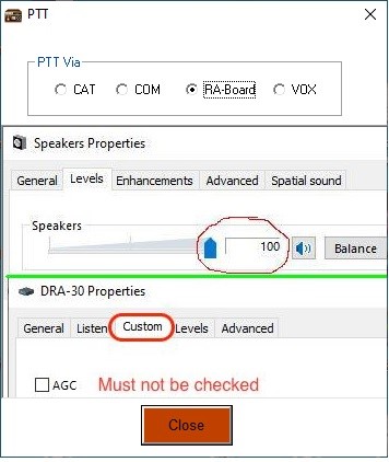
HT with existing software by choosing PTT with "RA board" within VARA FM (see Figure 1). The advantage of
this method of PTT (SEND) is that the PTT signal is independent of the level of the transmit audio,
often an issue with a SignaLink with a conventional VOX circuit. In the SignaLink VOX circuit the
transmit audio is rectified and converted to a DC signal which closes a physical relay which then
grounds the PTT line on the HT. I did get an original SignaLink to work using
its built in VOX circuit, but I must admit it was much fussier to set the optimum TX gain and
to then adjust the DLY (delay) knob which controls the hang-time or the time for both the
SignaLink and the HT to return to receive mode when the TX audio and VOX ceased.
Figure 1 - VARA FM PTT options:
Timing Requirements of VARA FM:
VARA FM is a "linked mode" where two stations are in a kind of digital dance, exchanging data in small
chunks (blocks or frames). When the receiving station copies a block of data with no errors it sends
an "ACK" (acknowledgment) to the sending station, which then sends the next block of data. But if the
receiving station sends an "NAK" (non ACK) due to corrupt data, the transmitting station resends that
block of data until an ACK is received. The VARA dance continues until the complete message is received
with no errors. If a succession of NAK's is sent, the sending station's software then adapts to worsening
conditions, and slows down the VARA FM speed (switches to a lower gear). This enables VARA FM to
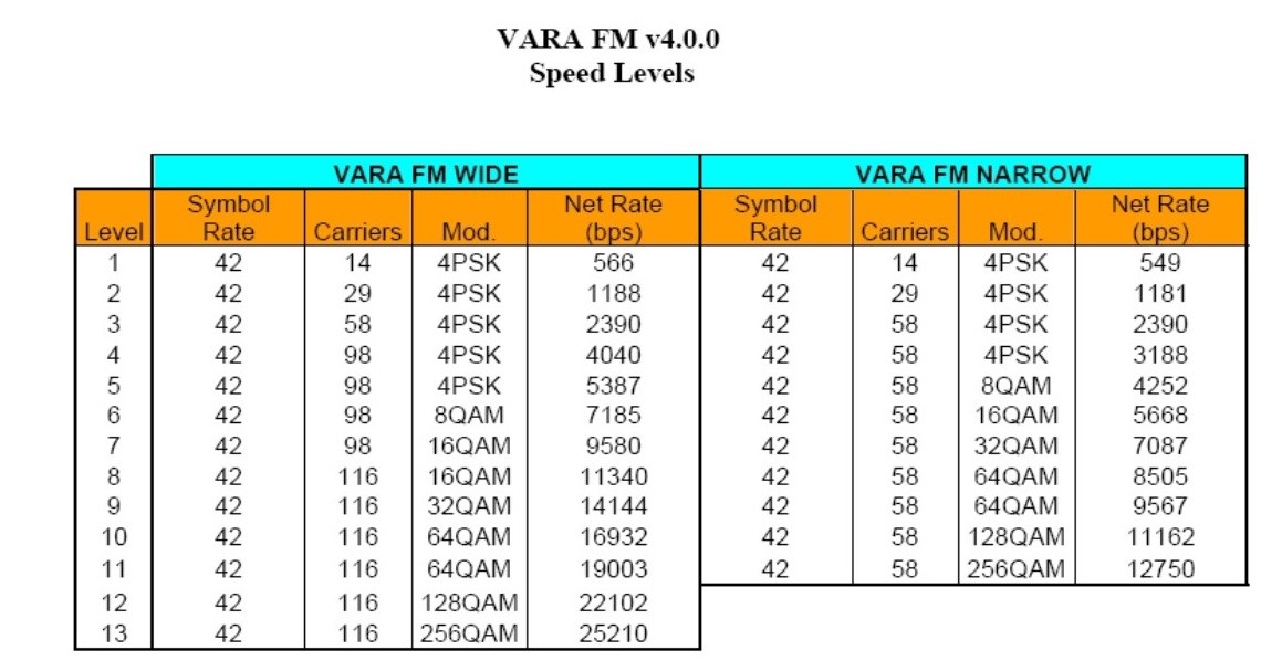
get traffic through under poor conditions by adapting the data speed. See Figure 2 for a list of
the current VARA FM (narrow) data speeds. The "wide" mode will not work on a HT microphone
circuit, as it needs the wider bandwidth of 9600 baud radios. On 9600 baud (a legacy packet
term) the modulation is connected directly to the modulator circuit.
Figure 2 - VARA FM speeds:
TIMING is CRITICAL -
The timing of these VARA ACK/NAK exchanges has a narrow range of acceptance. The time to switch
back and forth from Information Sending Station (ISS) to Information Receiving Station (IRS) can
only extend to a few hundred milliseconds with present VARA software. The link breaks if the PTT
mechanism or if the HT itself takes too long to change from transmit to receive and back to transmit
mode. The SignaLink VOX is especially challenging to set up correctly. VARA FM was designed to
be used in FM simplex setups with short "delay" times between the ACK/NAK and data streams.
However, if the reset timing on a common 2M FM analog voice repeater is fast enough, VARA FM
can be sent via a voice repeater (with the owner's permission, of course).
Figure 3 - DRA SR-RJ45 sound card (inside an original SignaLink case) and Baofeng HT BF-F8 with
appropriate cable from Tigertronics (SLCABHTW).
For the tests I removed the rubber ducky antenna and used an outdoor 2 meter vertical antenna.
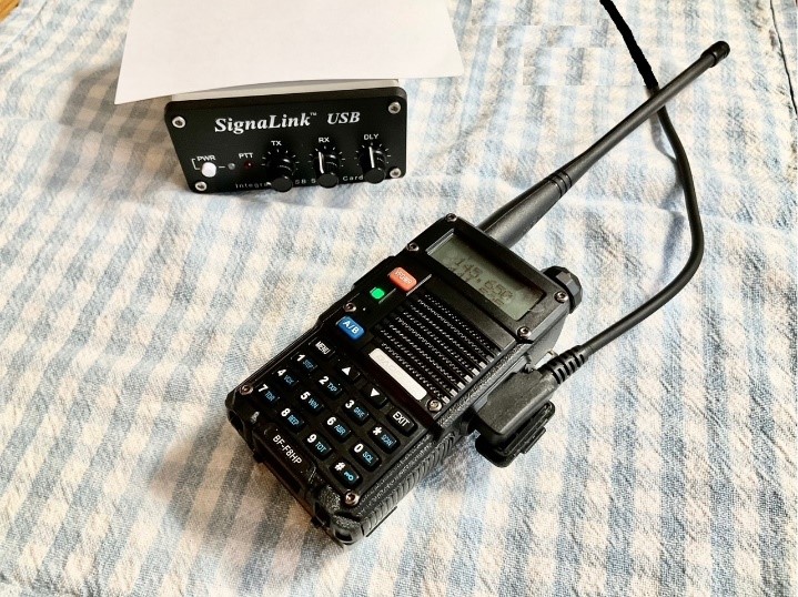
Figure 4 - NOTE the 2.5mm stereo (TRS) receive audio plug and the 3.5mm stereo (TRS) transmit
audio plug and the RJ45 plug to fit to the DRA or SignaLink sound card.
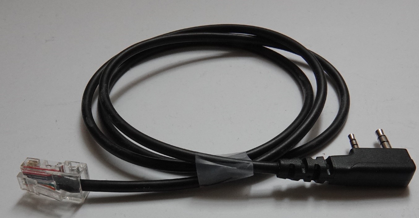
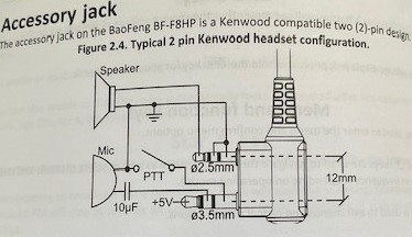
Figure 5 - Baofeng HT wiring scheme. Note the PTT signal is on the shield (TRS) of the 3.5mm plug,
but it grounds to the radio via the shield on the 2.5mm plug.
Some cables from 3rd parties do not wire this correctly.
TESTING STRATEGY: Audio Tests -
I next wanted to test if both the receive and transmit audio frequency response on the
Baofeng HT would work with VARA FM and FLDIGI. Since there is no DATA jack, receive audio must
connect to the headphone jack and transmit audio must connect to the microphone jack. The first
test I did was to check the receive audio using background noise as my "source". I
proceeded to unsquelch the radio, tune to an unused 2m FM simplex frequency, and to connect
the HEADHPONE jack of the HT to the MIC input of the DRA sound card. This allowed me to use the
FLDIGI audio spectrum feature to examine the receiver's audio frequency response.
Normally one would expect adequate levels of undistorted receiver audio (perhaps 100 millivolts)
on an HT from 400 Hz to 2500 Hz for voice modulation. Using the audio spectrum option in FLDIGI
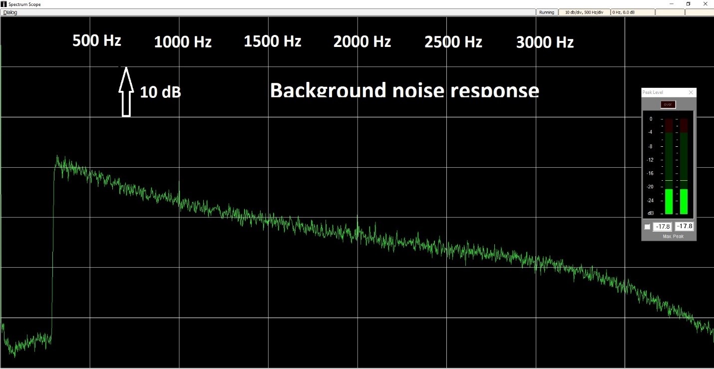
I tested the frequency response from 0 to 4000 Hz. I measured a very sharp null in audio below
300 Hz (common on all FM radios to avoid hearing PL tones) and then peak at about 400 Hz, and
then a gradual taper of the audio from 500 Hz out to 3000 Hz. This gradual taper from 500 Hz
to 3000 Hz is the expected audio frequency response typical of all FM radios via the speaker
or headphone jack. It shows FM receiver de-emphasis (decline) at a rate of 6 dB per octave
(an octave is a doubling of pitch). So from 500 Hz out to 2000 Hz (two octaves) I would expect
a decline of about 12 dB, which was confirmed in Figure 6. Thus, higher-pitch sounds (from any
source) are reduced in amplitude in the radio's speaker, helping to lower the high pitch
(annoying) noise. Most voice operators would squelch their radio so that they do not have to
listen to this noise between voice transmissions.
Figure 6 - The image below illustrates the typical steady decline (de-emphasis) of receive
audio from 400 Hz out to 3000 Hz, followed by a sharper decline to 4000 Hz. Most sound card digital
modes use a narrow range of audio from 1000 Hz to 2000Hz, centered at 1500 Hz, but some wider-band
digital modes rely on a 2 kHz signal, extending the bandwidth from 500 Hz out to 2500 Hz.
Transmit Audio Compensation -
To compensate for this decline of high frequency receiver response, all FM voice transmitters
reverse the process, employing a transmit pre-emphasis circuit (+6 dB /octave) to the microphone
audio from 500 Hz out to 3000 Hz. In the case of digital modes from a sound card passing through
the microphone circuit, this pre-emphasis would also affect them. The combination of pre-emphasis
on transmit and de-emphasis on receive results in all FM radios having a reasonably "flat" audio
response from 500 Hz to 3000 Hz via the mic/speaker ports to produce natural sounding audio.
I wanted to test if the audio frequency response on this HT would work for EMCOMM digital modes
which often require a bandpass about as large as a human voice.
TESTING TRANSMIT AUDIO (a critical step):
The next test was to set the level of the transmit audio from the DRA sound card's output to the
Baofeng HT's MIC jack with the Tigertronics cable. I began by setting the Windows PLAYBACK
sound card TX level attenuation (5% or -24 dB) to what seemed appropriate (a few millivolts)
for an HT microphone port. I then loaded Winlink Express, chose the mode VARA FM (P2P) and
adjusted the VARA TX level until the TUNE (test signal) sounded about as loud as my voice did
on a second radio receiver. [note: there are more precise ways to set TX audio deviation if
you have access to a RF spectrum analyzer]. I then created an email to send to myself on a second
2m FM radio via 2m FM simplex. I substituted an external 2m outdoor antenna for the rubber
ducky HT antenna to avoid RF in the shack. I also used toroid filters on all the audio and
USB cables. The receiving station was an Icom 746Pro and DRA70 sound card in my own shack,
using a second outdoor 2m antenna. Using the mode VARA FM (narrow) the Baofeng performed
admirably on the LOW power setting of the HT (1 watt) and the ACK/NAK timing was within
acceptable limits (few hundred milliseconds).
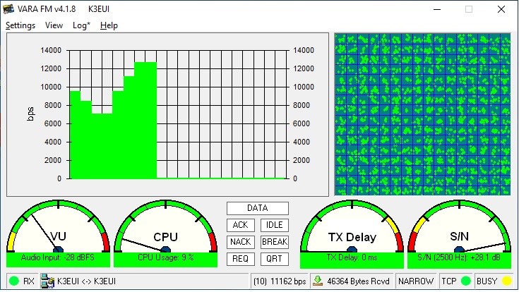
Figures 7 and 8 show the Baofeng HT sending and receiving a 55 kB file via Winlink Express in the Peer-to-Peer (P2P) VARA FM narrow mode. Rates were excellent, as shown in the photo. The S/N was a +28dB. Thus the Winlink EMCOMM mode VARA FM (narrow) was verified. I did additional tests with two nearby VARA FM Gateway operators which produced good results with the HT power increased to 8 watts. Typical data rates were 3000 to 9000 bit/second for files that took a few minutes. Note that the software changes speeds (gears or levels) without user intervention.
Figure 7 - HT transmitting high speed VARA FM (narrow)traffic. The vertical axis shows the data
rate in bits per second (bps). The horizontal axis is time.
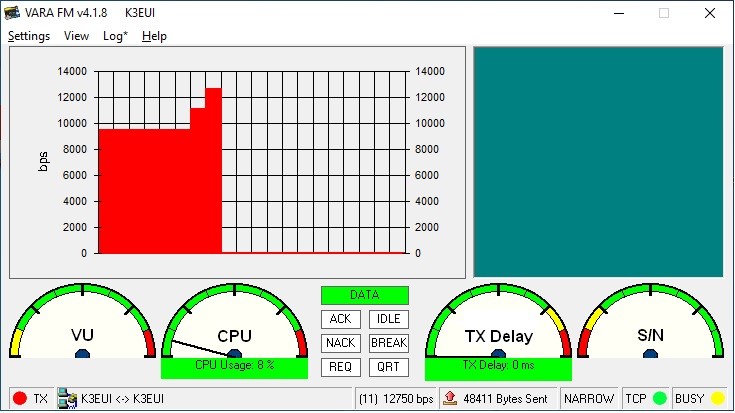
Figure 8 - HT receiving a VARA FM signal at very high speed. The checkerboard reveals the
data falling into specific data "bins" with the the highest speed 256QAM representing a 16x16 cell.
TESTING FLDIGI (FLMSG):
The last test I performed was to see if the Baofeng HT could correctly receive a high-speed
8PSK1000F FLMSG EMCOMM message, and a MFSK128 image using FLDIGI software. FLDIGI is the
software of choice for many EMCOMM groups, as it works on all platforms, is constantly updated,
and is free!
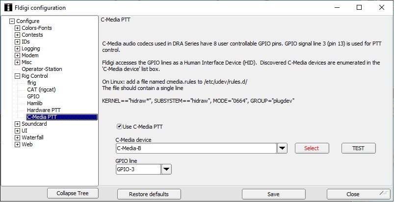
FLDIGI also allows for PTT (SEND) using CAT (rig control) commands, a COM port, a VOX, or via the C-Media chip's PTT device (Figure 9). I was limited with an HT and no data or CAT port to the C-Media option, which worked very well. Had I used the original SignaLink, I would have picked the VOX option built into every SignaLink, and then set the DLY (delay) knob to a longer hang-time (12 O'clock). FLDIGI is not a linked mode and does not send ACK/NAK back to the sending station. Transmissions are not interrupted by the continual ACK/NAK signals. Either the entire FLMSG is received or it is tagged with "errors" and the entire FLMSG is repeated. FLDIGI does have another option: FLAMP which splits a long message into smaller BLOCKS, and only missing BLOCKS need to be repeated, but only at the end of the entire message.
Figure 9 - PTT Configuration for the DRA-SR sound card using C-Media device:
FM Modes Commonly used for EMCOMM with FLDIGI:
There are many FLDIGI modes used on simplex FM circuits for EMCOMM, including THOR, MFSK,
MT63, OFDM, and 8PSK. The FLDIGI mode 8PSK1000F is commonly the highest speed mode (over
3000 word/minute) used on the Chester County (Pa) NBEMS EMCOMM net on 2m and 70cm FM.
This mode works well on simplex as well as via our analog FM repeater system (with the owner's
permission of course). The mode 8PSK is a tricky one to demodulate. It is a phase-shift mode
with 8 possible states (3 bits/baud) of phase. Too much or too little receive audio causes
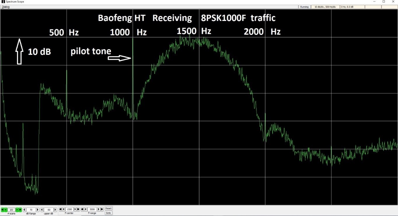
problems demodulating 8PSK. Note also the "pilot" tone at 1000 Hz which helps decode 8PSK
modulation phase changes.
Figure 10 - Baofeng HT receiving a FLDIGI / FLMSG EMCOMM traffic with the mode 8PSK1000F via
the headphone port. The data appears from 1000 Hz to 2000 Hz on the spectrum, centered at
1500 Hz. One must be careful to adjust the RX volume knob on the HT to keep the receive audio
level to about -20 to -30 dB.
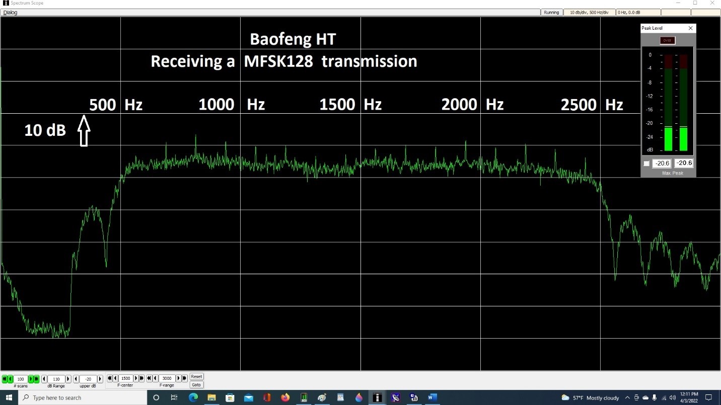
The last test was to see if the Baofeng HT could properly receive an image sent with the wide bandwidth FLDIGI mode MFSK128. This mode consists of 16 closely spaced tones, with constant amplitude, sent one at a time at 125 baud, (480 word/minute). The challenge was that this mode requires clean undistorted audio from 500 Hz out to 2500 Hz. It is perhaps the ideal mode on FM EMCOMM nets for both accuracy and speed. We use it each week to practiced sending FLMSG and FLAMP traffic, as well as to send small images.
Figure 11 - This image shows the receive audio of MFSK128 coming from the headphone jack of the
Baofeng HT at an amplitude of about -20 dB (Goldilocks level). If you look carefully you can see the
16 distinct tones as small spikes. The PEAK LEVEL meter is a secondary app (Darkwood Designs)
that shows the overall average sound intensity which we try to keep at about -20 dB for best copy.
Summary:
My wish list is that future HTs include a true DATA port (like the common 6 pin MINI DIN
ports of VHF/UHF FM gear) for use with an external sound card, or even better, a USB port
with built-in sound chips that could be used for both Tx and Rx audio and CAT control
of the HT. Although I would not recommend any HT's be relied on for digital EMCOMM modes
via the MIC/HEADPHONE ports, I was able to verify that this HT did work with the two common
EMCOMM apps: Winlink VARA FM and FLDIGI (NBEMS). There was no RFI (feedback) from the radio
to the sound card using an external antenna and toroids on all of the audio and control lines,
and at 8-watt output, the HT did not overheat or shut down with transmissions of 2 minutes.
I am confident I could have used this setup in an emergency to receive and transmit Winlink
and FLDIGI NBEMS messages.
Thank you to KC3JUD for the Baofeng HT to test, and to N3FLL for loan of test cables and a SignaLink.
De Barry Feierman, K3EUI April 10, 2022
Article by Barry Feierman K3EUI - All Rights Reserved!
Images are property of Kevin Custer - W3KKC
HTML April 12, 2022, W3KKC All Rights Reserved!