Custom Products for the Digital Radio Amateur Enthusiast

|
Custom Products for the Digital Radio Amateur Enthusiast |
|
By Kevin Custer W3KKC
Non Amplified RA/DRA -
Frequency Response @ 600 ohms:
TX Path = 20Hz to 20kHz
RX Path = 20Hz to 19.2kHz.
Audio Impedance:
Input = >50k
Output (either channel) = 32 ohms*
*TX control pot set full CW (wide open).
Amplified RA/DRA -
Frequency Response @ 600 ohms:
TX Path = 20Hz to 20kHz
RX Path = 20Hz to 19.2kHz.
Audio Impedance:
Input = >50k
Output (either channel) = 16 ohms*
*At any TX control pot position.
Detailed Desctription:
In this article, I'll explain how we get this remarkable frequency response.
Let's now look at the design of the DRA Series adapters.
This gets pretty deep technically, and we're going to do some math, so I'll apologize for
its content and length now.
DRA Series frequency response drastically exceeds the audio requirements of any mode designed for two-way radio - analog or digital. This is mainly because the heart of the RA and DRA adapters is a C-Media chipset that was originally designed for stereo headset applications where people would be listening to high-fidelity audio, and process audio from a broadcast type microphone or other high-fidelity audio source.
Masters Communications has been producing radio adapter interfaces (sound cards that connect to two-way radios) since 2014. Our original RA Series was designed for AllStar Link - an analog linking and repeater controller software designed for ham radio. The C-Media CM Series is the only chipset that was made to work with AllStar Link, and is why many of the higher quality radio interfaces uses one of these chips. The CM108 was the first one, then the CM119 (no suffix), then the CM119A (the one that we currently use).
The following specifications are used in these calculations. This information is taken directly
from the products data sheet, available for download from a link from any DRA support page.
The stated frequency response of the CM119A DAC (transmit audio path) is 20Hz to
20kHz when driven by a 48kHz sampling rate program.
Its ADC input (the receive audio path) is somewhat less at 20Hz to 19.2kHz.
The DAC output impedance is 32 ohms (in the case of non-amplified interfaces).
The LM386 output impedance is 16 ohms (in the case of amplified interfaces).
The input impedance of the CM chips MIC input (our receiver audio path) is around 100k ohms. In addition, there's a 100k potentiometer pot going to ground. Worst case, the input impedance seen at the radio adapters input connection is around 50k ohms, because these two 'resistances' are in parallel. The coupling capacitors inline to the MIC input are both 4.7uF. So worst case the series capacitance is slightly over 2uF (2.35). When you do the math, this creates a high-pass filter at 1.35 Hertz (Yes - less than 2 cycles per second). As such, the receive audio chain of the RA-Series adapters have a frequency response well below the 20 Hz cut-off specification of the CM119A. The receive input circuitry is the same for all RA and DRA models.
The parallel capacitance on the MIC line is 47pF. Considering the source impedance is 50k ohms or less (many radios are between 600 ohms and 10k) the worst-case high end frequency response would extend to almost 68kHz. This is well above the 20kHz specification of the CM119A.
For Non Amplified DRA's, each CM119A DAC output (left and right) go through a pair of 100uF coupling capacitors and a 1k potentiometer. This provides a low frequency cut-off of about 100 Hz assuming the load is 32 ohms. In reality, most transmitters have an audio input impedance of 600 ohms or more. At 600 ohms, this equates to a low frequency cut-off of 5.3 Hz, well below the 20 cycle low frequency specification of the CM119A chip. The rotational position of R14 and/or R16 does affect the output impedance, but because this control is 1k on non amplified models, it doesn't overly increase the output impedance as this pot is commonly set to 1/2 rotation or greater.
For Amplified DRA's, each CM119A DAC output (left and right) feed the inputs of the LM386 IC's. Those coupling capacitors are sufficiently sized to exceed the frequency response of those IC's. Each output of the LM386 goes through a 100uF coupling capacitor. This provides a low frequency cut-off of about 100 Hz assuming the load is 16 ohms. In reality, most transmitters have an audio input impedance of 600 ohms or more. At 600 ohms, this equates to a low frequency cut-off of 5.3 Hz, again, well below the 20 cycle low frequency specification of the CM119A chip.
For all intents and purposes, the frequency response of all DRA radio adapters are no less than 100Hz to 19.2kHz worst case scenario, and likely to be 20Hz to 19.2kHz depending on the connected radio. I've never seen a reference to the actual audio frequencies used to create the subcarriers in VARA FM Wide. I'll generically state (guess) that it requires a flat audio frequency response from 300Hz to approaching 6kHz. DRA's of any model do that easily, even if I missed my guess by a lot on either end.
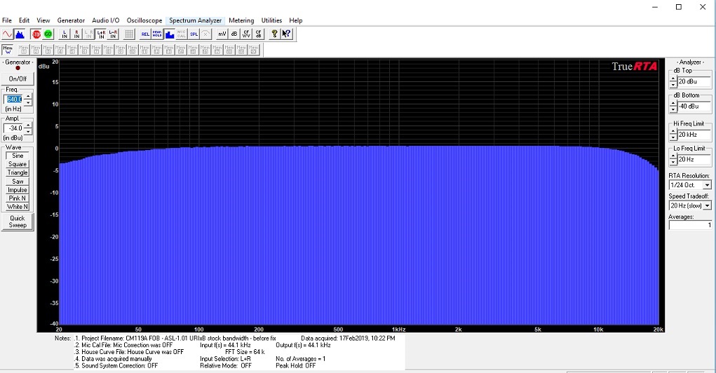
Here's a audio spectrum analyzer sweep of a CM119A with 100uF coupling capacitors being tested for maximum frequency response. The testing above was done using a Windows based audio spectrum analyzer program called TrueRTA. I own the 1/24 Octave license. This testing was done at a 44.1kHz sampling rate. It's actually a little better at 48kHz.
In terms of dynamic range - it's 16 bits (96 dB theoretical) through the chain, which is way way more than the noise-limited dynamic range of two-way radio. Even if you write off the additional digital headroom requirements in dealing with preemphasis and deemphasis or audio frequency compensation run inside of the program, there's still more dynamic range available than would be realized in two-way (about 40dB at best).
In terms of noise immunity, the USB input to the CM119A can be a limiting factor where signal to noise is concerned. We've worked very hard on the design of the circuit boards to insure the USB inputs are properly routed and terminated and deliver the lowest possible noise. The use of a high quality circuit board with a massive ground plane and rounded traces on the USB lines insure high signal to noise ratio. 47pF capacitors on all input and output lines help to insure noise immunity is high as well as providing protection against RFI, and proper USB communications path impedance. I use a vector network analyzer (VNA) to insure high return loss (best match) of the USB path.
At first, Jose (the creator VARA) was a little hung-up on the radio adapters that have the added amplification. He felt it was somehow limiting the audio bandwidth or adding distortion or other artifacts which would limit the throughput. I can guarantee that the added amplifiers in the DRA Series aren't causing any throughput limitations. In fact - with some radios, they FIX throughput limitations.
In summary, the DRA Series radio adapters are not a limiting factor in exceptional throughput digital communications using two-way radios. They will work well beyond the capabilities of the software and radios we're connecting DRAs to.
Email Kevin Custer for additional support.