Custom Products for the Digital Radio Amateur Enthusiast

|
Custom Products for the Digital Radio Amateur Enthusiast |
|
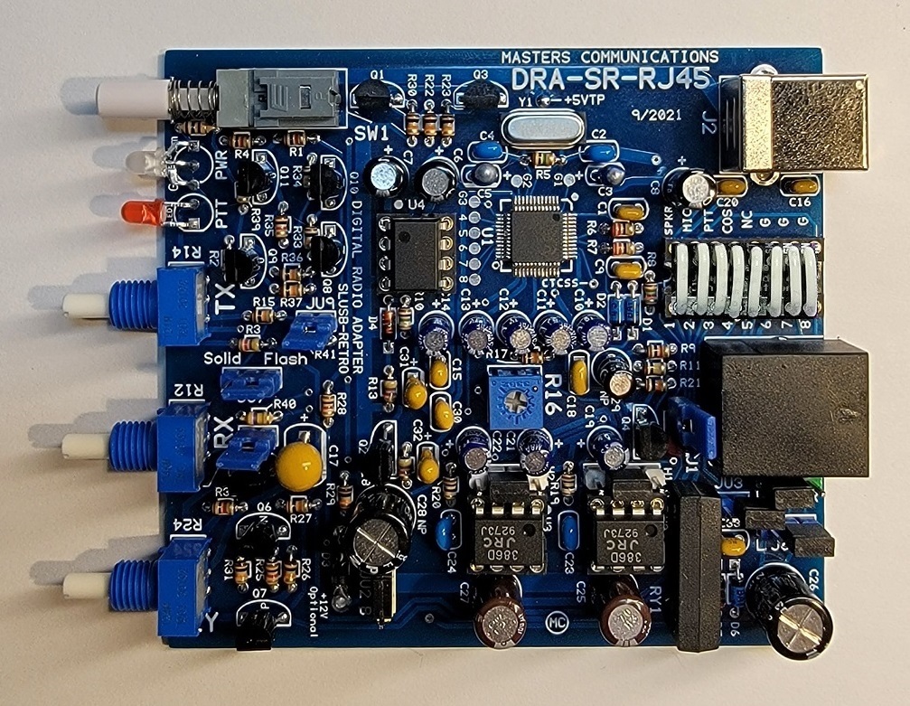
A Radio Interface for Digital Two-Way Radio Applications
Top side of DRA-SR-RJ45 board - shown slightly enlarged.
(Click photo to show a larger image)
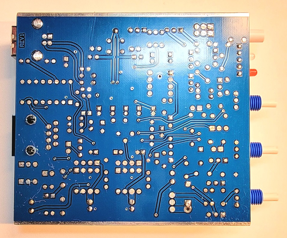
Bottom side of DRA-SR-RJ45 board - shown slightly enlarged.
(Click photo to show a larger image)
Schematic Image - Click to download a high quality PDF.

NOTE: The schematic depicts the functions of the RJ45 socket with the configuration socket wired "straight across" as shown in the upper image. Obviously, the configuration socket allows re-routing of these signals to other pins when necessary, and then they will not match the descriptions shown in the schematic above.
Parts List:
If you purchased our kit, refer to the parts list and make sure you have all of the components
you need to build it.
Click here
for Parts List.
Construction/Assembly:
Click here for assembly instructions and construction notes - with large photos.
Jumper Settings:
Click here
for Jumper Settings and other board connection assignments.
VOX Operation:
Click here
for DRA-SR VOX Operation.
RJ45 Pinout:
Click here
for RJ45 Pinout.
Installation:
This device is intended to be installed inside of a SignaLink USB case. Simply open the SignaLink
USB and replace the entire circuit board using the supplied Allen wrenches.
Go to the DRA initial set-up -
start-up page.
H1 and H2 header pin assignments:
Click here for a detailed header pin explanation. The
primary purpose of the headers H1 and H2 are for installation of
optional FL-10 audio filters. The FL-10 is designed to be installed onto the header pins
directly or remotely by extending the four pins with wires. Jumpers are needed over the center
two pins if the optional filters are not installed. These optional filters are rarely necessary.
Recommended powering requirements:
The board is supplied with 5 VDC from the USB connection of the host or computer. The audio amplifiers
and optional filters can run from 5V, or from an external power source of 6 to 15 VDC. Jumper JU2 controls
where the voltage is sourced from for these sections.
Recommended receive audio input level:
The DRA-SR accepts the widest range of audio compared to any other similar radio adapter. The
input signal is attenuated by a potentiometer, giving the broadest range of acceptable levels.
As little as 20 mV P-P, and as much as 20 volts P-P. If your receive audio level is adjustable
or programmable we recommend around 2.0 volts P-P. This allows very good signal-to-noise
ratio and low cabling cross talk. This level results in a 50% rotational setting of the potentiometer.
All DRA-SR's are supplied with a Genuine C-Media CM119A.
Information on the CM119A.
Click here
to download a manual for the C-Media CM119A.
Secure PayPal ordering is available from the DRA-SR-RJ45 main page.
Email Kevin
Custer ordering information, order by check, or support of this
exciting product.
Product of Masters Communications, all rights reserved.
SignaLink® and SignaLink USB® are registered trademarks of
Tigertronics.
The use of the name SignaLink and/or SignaLink USB is only in reference to this product.
No infringement for such use is intended.
Specifications may change without notice.
Images property of Kevin Custer - W3KKC
Board layout by Kevin Custer - W3KKC.
HTML June 24, 2021, W3KKC All Rights Reserved!