Custom Products for the Digital Radio Amateur Enthusiast

|
Custom Products for the Digital Radio Amateur Enthusiast |
|
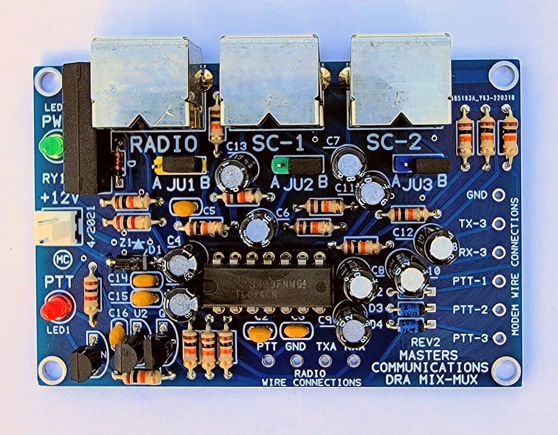
Top photo of the DRA-MIX-MUX circuit board (click for a larger view).
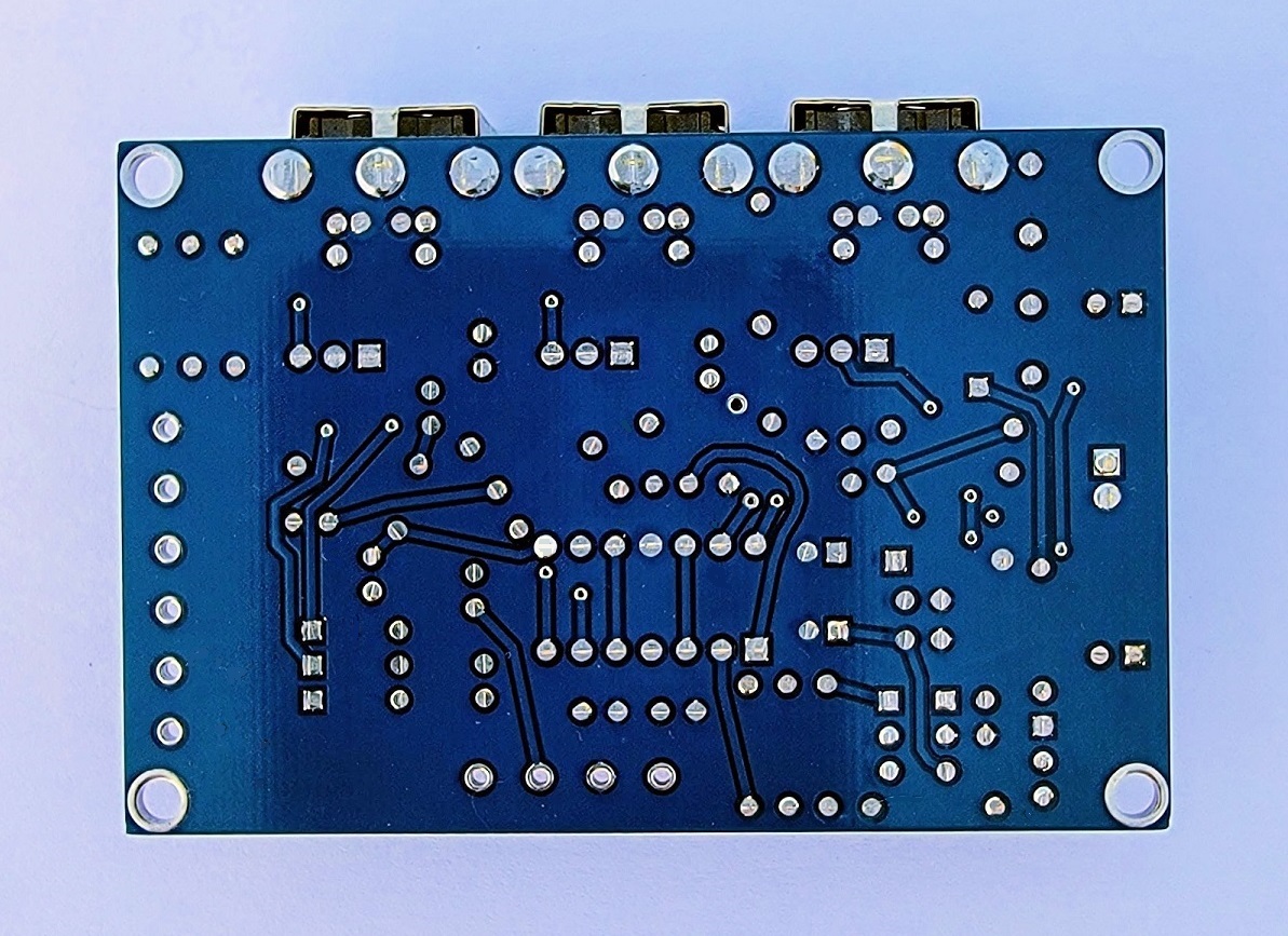
Bottom photo of the DRA-MIX-MUX circuit board (click for a larger view).
REV2 boards adds a relay for keying the radio PTT. Some ICOM radios require this.
Assembly:
If you purchased our kit, refer to the parts list and make sure you have all of the components
you need to build the kit. All of the components are supplied with the kit, and while we make
every effort to be sure we didn't omit any components, it can happen. If you are missing
anything, or ruin something, just contact us.
Click here for Parts List.
Assembly can be done by personal choice, but you may find it easier to install the
shortest components first, building toward the tallest, and finish with the connectors on the
ends. This "vertical order" insures that components stay seated against the board when soldering.
All components will be placed against the board except for the transistors and voltage regulator.
The Parts List has several construction notes as well.
Install all fixed resistors. Some resistors color bands may be hard to make out. If in doubt, use an ohm meter to verify the value before soldering it in place. You can refer to the photo above for additional part orientation and verification.
Install all of the diodes, observing polarity. The square pads are the banded end of the
diodes.
There is a silkscreen mistake on the early REV2 boards where the diode beside
the relay (near the RADIO connector location) is also marked D3. It should say D5.
I generally cover the "3" with a black sharpie, resulting in the component label of "D".
Boards shipped after December 20th of 2022 have this corrected. D5 (D) is a 1N4148 orange glass diode.
Install the shortest/smallest capacitors next. Small capacitors are identified as follows: "47" or "470" = 47pF, "103" = 0.01uF, "104" = 0.1uF, in other words the first two digits are the value and the third digit (if present) is the number of zeros you add to determine the value. These ceramic capacitors are not polarized and can be installed either way.
Then, install the 2 LEDs - PWR=Green - PTT=RED. The long lead goes into the round hole.
Note: This is different from the capacitors, where the long lead go into the square hole!)
Install the IC socket.
On REV2 boards - Install RY1 - the 1A05 5V relay beside the RADIO connector location.
Install JU1 thru JU3 male 3-pin headers - observing the color and location.
Next, install the transistors (flat to flat on silkscreen). There are letters inside the silkscreen outline. "N" is for NPN - (2N2222). "P" = PNP - (2N2907).
Install the voltage regulator flat to flat on silkscreen in the U2 "VR" position.
REV1 boards use a 78L33 (3.3V) and REV2 borads use a 78L05 (5V).
Install the 2-pin MOLEX power connector - positioning the orientation tab on the side nearest the date silkscreened on the board. The silkscreen can also be used to determine the correct way to install this connector. Next - Install the larger electrolytic capacitors observing polarity! The square pads are the + of the electrolytic capacitors. The positive lead is the longer one. NOTE: There are two capacitors that you need to make sure you install correctly as they are polarized. Look at the board and locate the "+" silkscreen print. They are C1 and C4. The positives of these capacitors are away from U1. Long leads go into the square holes.
Next, install the other larger capacitors. If required, bend the leads of these straight so they sit down against the board. Lead orientation on "NP" capacitors is not critical and is why there are no square pad holes for NP capacitors.
Then, finish by installing the female Mini-DIN-6 socket connectors - if desired.
Email
Kevin Custer for support.
Product of Masters Communications, all rights reserved.
Specifications may change without notice.
Images property of Kevin Custer - Masters Communications.
Board layout by Kevin Custer - W3KKC
HTML December 7, 2021, W3KKC All Rights Reserved!