Masters Communications
P144 VHF Preamplifier and
P440 UHF Preamplifier
By Robert W. Meister WA1MIK

|
Evaluation and Testing of the Masters Communications P144 VHF Preamplifier and P440 UHF Preamplifier By Robert W. Meister WA1MIK |
|
Background:
These preamps are T-I-N-Y-! The bare circuit board measures 1.03 inches or 26.2mm wide by 0.82 inches or 20.8mm tall (0.8446 square inches), truly postage stamp size. They're supposed to be 1.0 inches or 25.4mm wide by 0.8 inches or 20.3mm tall. A typical U.S. "Forever" postage stamp on a roll is 0.98 inches wide by 0.87 inches tall (0.8526 square inches). The boards are 0.063 inches or 1.6mm thick. Quality, as always, is top-notch. Note that the VHF preamp (on the left in the photo below) has three surface-mount resistors already installed in the lower right corner. All other parts on both preamps are through-hole type for easy assembly and replacement. Here's one photo showing the two unpopulated boards. Click on any photo for a larger view.
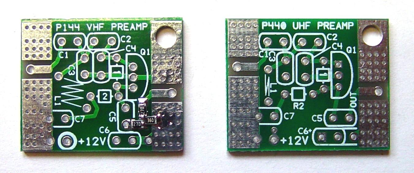
These kits come with all the parts including about 6 inches or 15cm each of stranded black and red hookup wire you can use to feed power to the preamp. As mentioned above, three surface-mount components on the VHF preamplifier are pre-soldered to the board. Good thing too, because they're super tiny.
Assembly:
I built each kit separately. I printed the parts list, verified the parts were all present and accounted for, and followed the assembly directions and notes on the parts list. The coil dimensions and winding directions are stated on the parts list along with suggestions to get the diameter correct. I found a Motorola black plastic tuning tool that had a shaft with a diameter of 0.156 inches exactly (about 4mm) so I used that for the VHF coil (L1). I also considered wrapping a 1/8-inch (0.125 inch or 3.175mm) diameter screwdriver shaft with a few layers of electrical tape until the proper thickness was obtained.
Assembly is easy. Following the parts list and the circuit board silk screen, I installed the components in this order, from the smallest or closest to the board, to the largest:
Construction Notes:
The transistor is oriented as shown on the circuit board silk screen, with the flat side facing the center of the board. It should be pushed down so its bottom edge is about the same height off the board as the height of the resistors. You can look at the board from the side and determine when that edge becomes even with the top of R1.
The coil on the VHF preamp should be placed so it's almost touching the circuit board. The assembly instructions call for 1/32 inch or about 0.8mm, which is half the thickness of the board itself.
You may find it easier to twist the UHF coil (L1) before you insert it into the preamp, as you'll have full use of both hands and all fingers and can do it neatly.
The SMA jacks are installed with the center pin sliding over the long solder pad on the component side of the circuit board. The ground pins are designed for the 1.6mm board thickness but if they slide off, squeeze them together slightly so they grip the board and the connectors stay in place while you solder them.
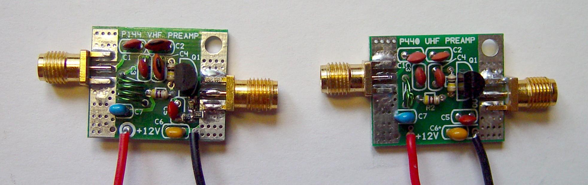
I preset the two coils according to the parts list and as shown in the photos on the web page. Each board was cleaned with 91% isopropyl alcohol and a toothbrush then sprayed with commercial flux remover for a final rinse. Construction took about an hour for the two kits and I was going very slowly. Here's a photo of both preamps after assembly.
Testing:
Testing was performed at 12.0VDC input. Initially I used a bunch of adapters between my spectrum analyzer / tracking generator's N-F connectors and the SMA-F connectors on the preamps, as well as some lousy pieces of coax cable. The input level from the tracking generator was set to -30dBm so I was working well below the compression points of the preamps. The maximum input signal level is about -16dBm. I also tested them with an input level of -70dBm and the gain was perhaps 1dB higher. These preamps should be tuned for best return loss, but if that is not possible, tune for the highest gain, in the center of the band. Do not exceed about -30dBm for an input signal level during tuning.
As built, the VHF preamp had a peak at 150 MHz. Slightly compressing the coil brought that peak down to 146 MHz. The gain at that frequency was just over 10dB and it was flat from 140 to 150 MHz, so tuning is not critical. The preamp drew about 10mA.
As built, the UHF preamp had a peak at 420 MHz and the gain was around 13dB at the peak, about 12dB elsewhere. Half a turn tighter on the coil moved that peak up to 450 MHz but it was less pronounced. The gain was also just over 10dB and was within 1dB from 420 to 480 MHz. The preamp drew about 9mA.
The preamp tuning and gain seemed to be unaffected unless I put my fingers within 1/4 inch of the components. Varying the DC input voltage from 11 to 15 volts barely affected the gain by less than 1dB.
By eliminating one troublesome cable and a few adapters, I took measurements again. The tracking generator's actual output, when set at -30dBm measured -30.6dBm. With this input signal, the output of the VHF preamp measured -19.4dBm, resulting in a total gain of 11.2dB. It is rated for 11dB gain. It had 10dB or more gain over the range of 140-151 MHz. The output of the UHF preamp measured -17.7dBm, resulting in a total gain of 12.9dB. It is rated for 13dB gain. It had 10dB or more gain over the range of 410-500 MHz. These results are more precisely tabulated below.
I connected my Eagle Return Loss Bridge to my spectrum analyzer and determined that when I set the tracking generator output to 0dBm, the return loss of the VHF preamp was horrible, around 7dB. By setting the tracking generator output to -30dBm and retuning the preamp for the best return loss, the return loss was greatly improved, and was about 18.5dB over the 120-180 MHz range. The gain was also measured using the same -30dBm level at 11.15dB. The best return loss and the gain peak occurred very closely, at 146.40 and 146.10 MHz respectively.
The UHF preamp performed similarly well. Using the same -30dBm input level and my Eagle Return Loss Bridge, I tuned the preamp for best return loss, which was just over 18dB over the 400-500 MHz range. The gain measured 12.87dB. The best return loss and the gain peak occurred very closely, at 450.0 and 440.0 MHz respectively, although the difference was only noticeable by the spectrum analyzer at a few hundredths of a dB. The table below summarizes the gain measurements made by me as well as by Kevin. All values in the following tables are in dB rounded to the nearest tenth of a dB.
| Preamp | My Gain | Kevin's Gain | Rated Gain |
|---|---|---|---|
| VHF | 11.2 | 11.8 | 11.0 |
| UHF | 12.9 | 13.5 | 13.0 |
The Input Return Loss measurements are shown in the table below. The preamp output port was terminated with 50 ohms and the preamp was powered up. These measurements were made at the frequency of the best input return loss.
| Preamp | My RL | Kevin's RL | Rated RL | Frequency |
|---|---|---|---|---|
| VHF | 18.6 | 25.7 | > 18 | 146 MHz |
| UHF | 19.1 | 22.0 | > 16 | 450 MHz |
The Output Return Loss measurements are shown in the table below. The preamp input port was terminated with 50 ohms and the preamp was powered up. These measurements were made at the frequencies shown in the table above (at the best input return loss).
| Preamp | My RL | Kevin's RL | Rated RL |
|---|---|---|---|
| VHF | 20.1 | 22.8 | > 20 |
| UHF | 8.5 | > 10 | > 10 |
Here's a photo of the test setup when measuring the input return loss of the VHF preamp.

Testing with a NanoVNA:
Many people have NanoVNAs. These are inexpensive and small pieces of test equipment that work well for measuring RF filters and antennas. I acquired an S-A-A-2 NanoVNA and tried using it to measure the input return loss, output return loss, and gain of the preamps. Unfortunately the output level from this NanoVNA is non-adjustable and set at -10dBm, and that much signal level exceeds the compression point of the preamps, so the gain measurement is incorrect. I was able to add a 10dB or 20dB attenuator to the input of the preamps to reduce the input level and that gave me acceptable gain values that matched what Kevin and I had previously gotten with our spectrum analyzers, which also measured the gain at -30dBm input.
Return loss measuring unfortunately can't be done with a pad between the NanoVNA and the preamp, since I'd then be measuring the return loss of the pad, not the preamp. With a test signal of -10dBm, the input return loss of the preamps was very poor, and this is due to the transistor and bias level that just aren't meant to work with signals of that high an amplitude. Once the input level was reduced to -30dBm (which is the level I used with my return loss bridge), the return loss values were greatly improved and met or exceeded the specifications. But such an input level reduction is not possible with the NanoVNA I have.
If you do your own testing and want to confirm the gain and return loss values, you'll need to do such testing at levels of -30dBm or lower. Remember, a preamp is used to increase low-level signals, not signals that are around 0.1V. If they're that strong to start with, you certainly don't need a preamp to make them stronger.
Test Equipment Utilized:
Agilent E4401B 1.5 GHz Spectrum Analyzer with Tracking Generator
Eagle RLB150N3D 5-1500 MHz Return Loss Bridge
Two 30 inch long RG-214 cables with N-Male connectors
Precision 50.0 ohm load with >40dB Return Loss
N-Male to BNC-Female adapter
BNC-Male to SMA-Male adapter
Credits and Acknowledgements:
Product information for the Masters Communications P144 and P440 preamplifiers can be found here.
Contact Information:
The author can be contacted at: wa1mik [ at ] comcast [ dot ] net.
This page originally posted on Sunday 06-Sep-2020
Article text, artistic layout, all photographs, and hand-coded HTML © Copyright 2020 by Robert W. Meister WA1MIK.
This web page, this web site, the information presented in and on its pages and in these modifications and conversions is © Copyrighted 1995 and (date of last update) by Kevin Custer W3KKC and multiple originating authors. All Rights Reserved, including that of paper and web publication elsewhere.