Masters Communications
CH25 Rev 4 Crystal Heater
By Robert W. Meister WA1MIK

|
Evaluation of the Masters Communications CH25 Rev 4 Crystal Heater By Robert W. Meister WA1MIK |
|
Background:
Kevin sent me an original CH25 (Rev 1) back in 2015. After building and evaluating that model, I made two improvements to the circuit. Kevin has integrated those changes and more into his latest revision. The product keeps getting better and better. He sent me two Rev 4 kits to build and evaluate: one with 1/8w resistors and the other with 1/4w resistors.
Assembly:
Assembly and initial testing the first kit took about an hour but the second kit took half that time. Kevin supplied a 10k resistor to be placed in the "RX" position, as well as a Zener diode, which I installed in my units. I installed the components for each kit in this order: the IC, the transistor, all resistors, the Zener diode, all capacitors, the 78L05, both connectors, and finally the "temp set" pot. Kevin now supplies all kits with the surface-mounted components (the IC and transistor on this product) pre-installed. The kit was sold with either a vertical or horizontal shaft multi-turn pot; it now comes with both style pots so you can choose whichever is best for your situation. I used the horizontal shaft pot in the very first CH25 (Rev 1) and decided to use the vertical shaft pot in the one with 1/8w resistors and the horizontal shaft pot in the one with 1/4w resistors. The board can accommodate either style pot. I found the vertical shaft pot much easier to get to and adjust.
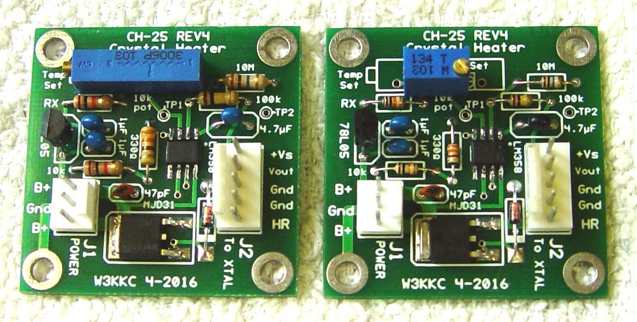
I used my ohmmeter to determine the value of each 1/8w resistor before installing it into the board, which is very well marked with every component's value and location. The 1/4w resistors are much easier to read but I still measured each one when I was sorting through the parts. It was also quite hard to read the values on the capacitors, however it was easy to determine which went where, just based on the size and lead spacing. (At the time I built these, there was no parts list, but the CH25 is so simple and well laid out that you don't really need one.) After assembly was completed, I cleaned the solder side of the board twice using some 91% isopropyl alcohol and a toothbrush. The photo below shows the completed boards; the one on the left has 1/4w resistors and the horizontal pot; the one on the right has 1/8w resistors and the vertical pot.
I used the existing crystal heater and temp sensor assembly (from when I built the original CH25 Rev 1) and just inserted the contact pins where required to mate with the Rev 4 design. This shortened the construction time considerably because I didn't have to wire up those components nor wait for the epoxy to cure. This assembly was wrapped with about an inch thick blanket of pink fiberglass insulation and was stuffed inside a large plastic pill bottle. This eliminates the effects of external air currents. Insulating the crystal assembly reduces the required heater current and keeps the temperature more constant.
Performance Measurements:
As expected, the units worked flawlessly the first time. With my bench supply set for 13.6 VDC, each CH25 drew about 200 mA when it began to heat the crystal. During this time I set the temp pot for about 150 degrees F, or 1.5025 VDC as monitored on TP1. I also monitored the voltage on TP2 to watch how fast the crystal was heating up. After two to three minutes the crystal reached operating temperature and the supply current started dropping, eventually stabilizing around 120 mA. At this point the voltage on TP2 was 1.5024 VDC, just about the same as the voltage on TP1.
I only took measurements on the board with 1/8w resistors but they both should be quite similar. The output of the 5V regulator was 5.08 VDC. The voltage on the high end of the pot was 2.55 VDC. The 10k resistor installed in RX limits the maximum possible temperature to about 255 degrees F.
After 10-15 minutes, the MJD31 transistor and the circuit board foil below it was warm to the touch. There was 5.82 VDC on the emitter feeding the heater resistor, 6.36 VDC on the base, and 13.60 VDC on the collector. At this condition, the transistor was dropping about 7.8 VDC at about 120 mA, which equates to a power dissipation of about 0.9 Watts. The circuitry on the board draws about 10 mA when the crystal is cold and drops down to about 3 mA when the crystal reaches the desired temperature. The rest of the supply current passes through the transistor and the heater resistors.
The heater resistors, a pair of 100 ohm 1/2 Watt film resistors, had 5.82 VDC across them, at almost all of the 120 mA supply current, which equates to a power dissipation of about 0.7 Watts. This was equally split between the two heater resistors, clearly within their safe operating range.
Contact Information:
The author can be contacted at: his-callsign [ at ] comcast [ dot ] net.
This page originally posted on Saturday 07-May-2016
Article text, artistic layout, all photographs, and hand-coded HTML © Copyright 2016 by Robert W. Meister WA1MIK.
This web page, this web site, the information presented in and on its pages and in these modifications and conversions is © Copyrighted 1995 and (date of last update) by Kevin Custer W3KKC and multiple originating authors. All Rights Reserved, including that of paper and web publication elsewhere.